Т³гж 10, Installation – OmniSistem Beta 3 – R4/R8 User Manual
Page 10
COMPACT LINE ARRAY SOUND REINFORCEMENT SYSTEM
8
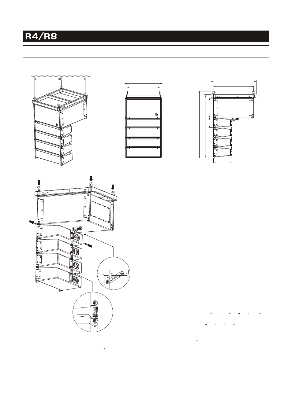
INSTALLATION
(1) Open the package and take out R4
R8 speakers
and the accessories.
(2) Mount the four M8 rings to the flying frame (see
Figure 1).
(3) Demount the two M5 thumb screws at the bottom
of R8, and take out the R4-R8 Link.
INSTALLATION METHOD 1
ONE CLUSTER FLOWN VERTICALLY
(4) Demount the two M5 thumb screws at the top of
the front side of R4.
(5) Insert the two R8 Front Links into the U grooves
along the left & right front edges of R4, make sure
the two screw holes on both sides are aligned, and
tighten the screws through the holes.
(6) Insert one end of the R4-R8 Link into the U groove
on the back of R4 and the other end into the U
groove on the bottom of R8, make sure the two
screw holes at both ends of the link are aligned
with the corresponding holes in the U grooves,
mount the two M5 thumb screws, and tighten them
(see Figure3).
Alignment of the white scale lines on the R4-R8
link with the edges of the two U grooves indicates
successful mounting.
Turn R4 speaker together with its back link (R4 Back
Link), make sure the right scale line marked on the R4
Back Link is aligned with the edge of the U groove at
the back of R4 speaker (The numbers marked besides
each scale line indicate different splay angles). Then
insert the M5 thumb screw through the aligned holes
of the R4 Back Link and the U groove at the back of
the speaker (Alignment with Number 1 hole in the
groove is required when 0
/2
/4
/6
/8
/10
of
splay angle is wanted, and alignment with Number 2
hole is required when 3
/5
/7
/9
of splay angel
is wanted).
For example, if the splay angle between two R4 speakers
is designed to be 5
, the scale line marked with the
number of 5 on the R4 Back Link must be aligned to
the bottom edge of the groove on the back of the top
speaker, then a certain hole in the R4 Back Link will
be found to be aligned with Number 2 hole in the groove
at the back of the top speaker. Insert a M5 thumb screw
through the two aligned holes and tighten it.
SPLAY ANGEL ADJUSTMENT
492
437
608
536
2
6
2
1
3
3
8
5
2
9
0
0
250
1
3
2
4
No.1 Hole
No.2 Hole