Terminater to the console, Led starbrite – OmniSistem PR Star Brite User Manual
Page 5
5/16
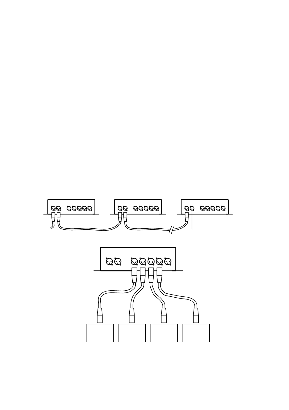
Connection between a LED StarBrite and a LED StarBrite Controller must be made with a special 5-pin signal
connection cable with a length of 15 meters (connect any one of the OUT1~OUT4 to the 5-pin input port of the LED
StarBrite driver box). And between the LED StarBrite Controllers or between the LED StarBrite Controller and the
console, 3-pin XLR cables are used for connection (connect by DMX IN / DMX OUT port). In addition, 3-PIN socket of
the OUT5 port only provides signal output (without power supply), it applies for Master/Slave mode only.
The 5-pin signal connection cable and the 3-pin XLR cable are connected as shown in the figure above.
Note: care should be taken to ensure that none of the pins touch the metallic body of the plug or each other. The body of
the plug is not connected in any way. The product accepts digital control signals in protocol DMX512 (1990).
First of all, connect a LED StarBrite Controller and a LED StarBrite, and it can run in the stand-alone mode with 12 preset
programs, according to the different applications, the Master/Slave mode and the DMX control mode can be selected.
In the Master/Slave mode, the master LED StarBrite Controller and the slave StarBrite Controller must be connected by
a 3-pin XLR cable from the master LED StarBrite Controller’s OUT5 port to the first slave LED StarBrite Controller’s DMX
IN port, then from the first slave LED StarBrite Controller’s OUT5 port to the second slave LED StarBrite Controller’s
DMX IN port, and so on, until all the LED StarBrite Controllers are connected. Eventually set the menu of all the slave
LED StarBrite Controllers to the “Slave” mode. At this time, Master/Slave mode is in effect.
In the DMX control mode, connections among the console and several LED StarBrite Controllers are similar with the
control mode above. Use a 3-pin XLR cable to connect the DMX output port of the console to the first LED StarBrite
Controller’s DMX IN port, then from the first LED StarBrite Controller’s DMX OUT port to the second LED StarBrite
Controller’s DMX IN port, and so on, until all the LED StarBrite Controllers are connected, Eventually, connect the LED
StarBrite Controller’s DMX OUT port to a DMX terminator (The address of any LED StarBrite Controller should be
correctly configured, for details, see the following sections).
To make the DMX control mode valid, set the menu of the LED StarBrite Controller to the DMX CHANNEL .When the
yellow indicator on the panel of the LED StarBrite Controller is on, DMX signal is OK.
Connections among the console and several LED StarBrite Controllers are shown in the figure below.
DMX
IN
DMX
OUT
OUT1
OUT2
OUT3
OUT4
OUT5
DMX
IN
DMX
OUT
OUT1
OUT2
OUT3
OUT4
OUT5
DMX
IN
DMX
OUT
OUT1
OUT2
OUT3
OUT4
OUT5
DMX
IN
DMX
OUT
OUT1
OUT2
OUT3
OUT4
OUT5
LED StarBrite
TERMINATER
TO THE CONSOLE
LED StarBrite
LED StarBrite
LED StarBrite