8 connecting the sensors to the canbus – NORAC UC5-BC-FT02A User Manual
Page 21
18
8 Connecting the Sensors to the CANbus
1. Route cable C03 from the input module to the 8-way coupler (E11). Fasten the 8-way
coupler to the boom with cable ties.
2. Connect the main lift sensor to the 8-way coupler using cable C02 and a 2-way coupler
(E12). Cable C02 and item E12 may not be needed if the 8-way coupler is mounted close
enough to the main lift sensor.
3. Connect the linear roll cylinder sensor to the 8-way coupler using cable C03 and a 2-way
coupler (E12).
4. Connect two cables (C05) to the 8-way coupler and route along the booms to the wing
sensors. Follow existing cables and hoses to be sure the cable will not be pinched or
stretched.
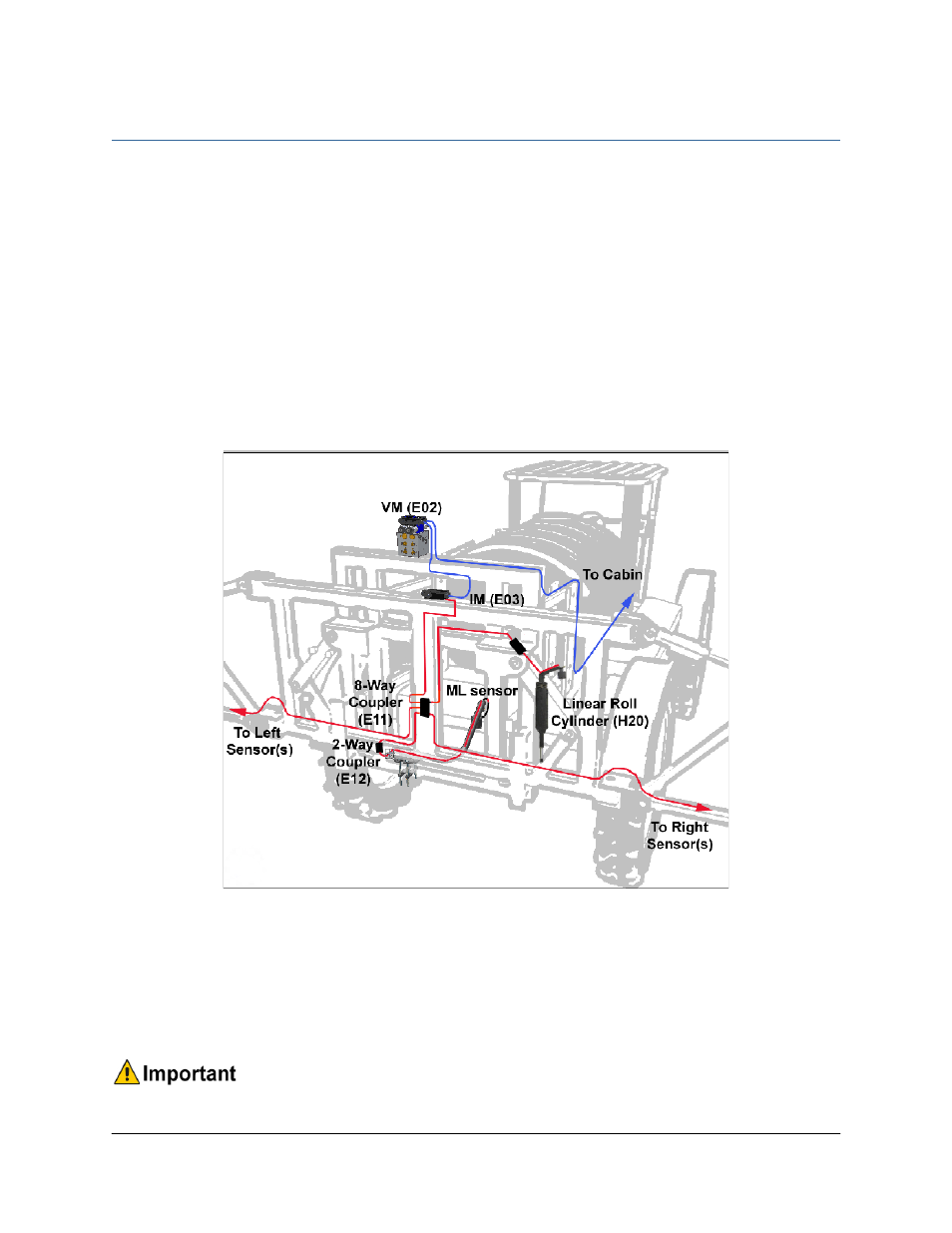
Figure 16: UC5 Module Locations and Cable Connections
5. At the sensor brackets, attach a 2-way coupler with terminator (E20) to the sprayer boom.
The 2-way coupler with terminator is the white two way coupler. Plug the sensor and the
CANbus cable into the 2-way coupler.
6. Insert the 6 pin plugs (P03) into the remaining receptacles of the 8-way coupler.
Ensure that all unused connectors are plugged with the plugs provided.