4 optional switch box – NORAC UC5-BC-FT02A User Manual
Page 20
17
7.4
Optional Switch Box
An optional remote switch box is available if it is desired to manually control the roll function
and auto/manual function from a switch in the cab. The switch box and cable can be ordered
using the following part numbers:
Item
Part Number
Name
Quantity
C25
44602-01
BOX SWITCH UC4 REMOTE HAND CONTROL VER.1 RMR
1
C26
43240-26
CABLE UC5 SWITCH BOX
1
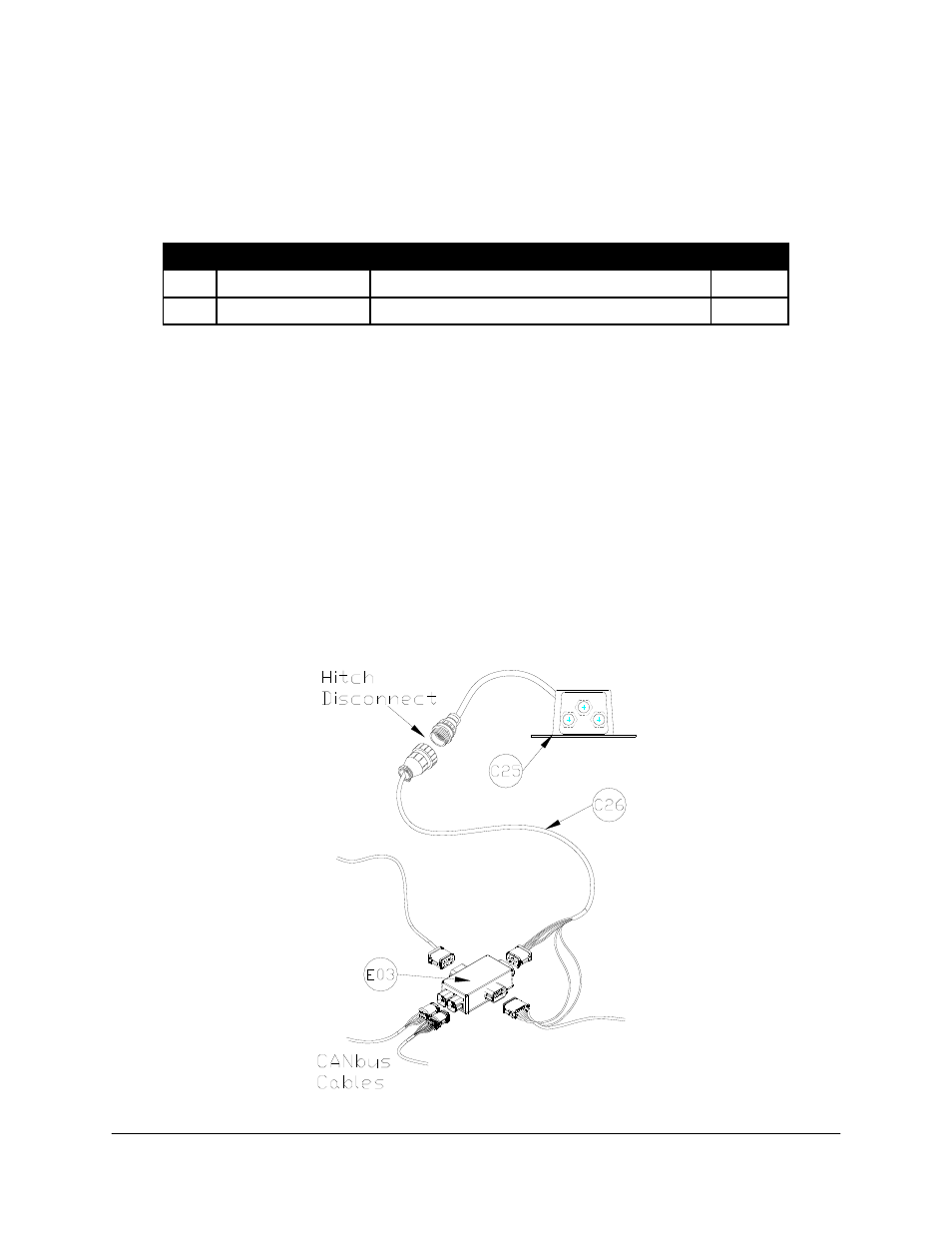
1. Disconnect cable C20 (grey side connector) from the Input Module (E03). Remove the
wedge from the face of the 12 pin Deutsch plug.
2. Insert the Roll CW pin from C26 into position 3 of the 12 pin plug on C20. Insert the Roll
CCW pin from C26 into position 4 of the 12 pin plug on C20. Insert the wedge back into
the plug. Connect C20 to the grey side connector on the Input Module.
3. Connect the 12 pin Deutsch plug on C26 to the grey end connector on the input module.
Route the other end of the cable to the hitch of the sprayer.
4. Attach the switch box (C25) inside the cab and connect it to cable C26. An extra label is
provided with the switch box if it is preferred to remove the switches from the housing and
mount them in the existing sprayer switch panel.
* Some sprayer types may not use all the switch functions.
Figure 15: Switch Box Installation