4 electrical installation – NORAC UC4+BC+FT2A User Manual
Page 17
13
4.4 E
LECTRICAL
I
NSTALLATION
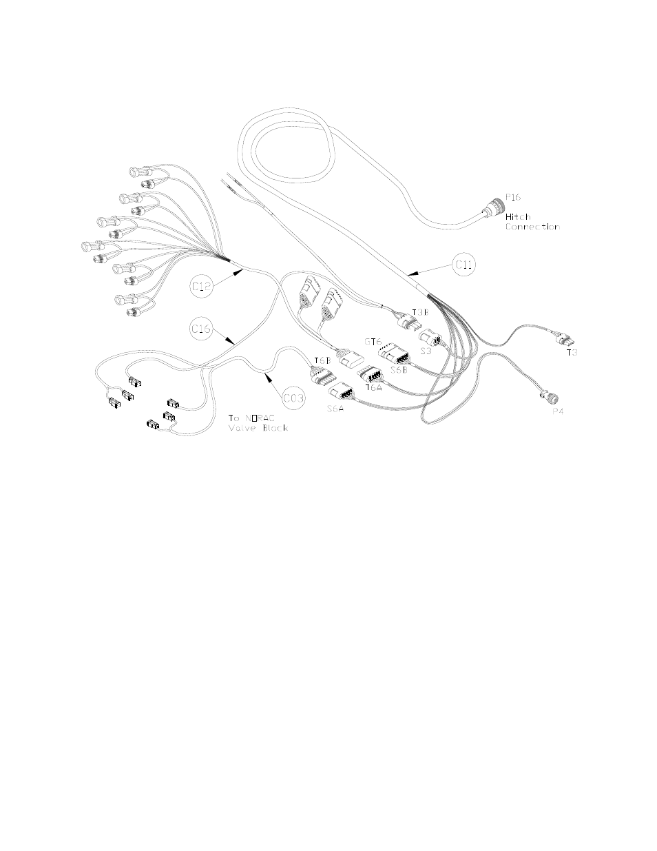
Figure 14: Cable Configurations: Rear of the sprayer
1. Route C11 to the rear of the sprayer,
in the vicinity of the valve block. Note
that the 16-pin AMP plug (P16)
provides the hitch connection.
2. Connect the 3-pin shroud (S3) on C11
to the mating 3-pin tower (T3B) on
C16. The two loose wires on C16 are
not connected for this installation.
3. Connect the 6-pin shroud (S6A) on
C11 to the mating 6-pin tower (T6B)
on C03.
4. Connect the 6-pin shroud (S6A) on
C12 to the 6-pin tower (T6A) on C11.
5. Connect the Deutsch connectors on
C12 to the Fast valve block, according
to the connector labels on the cable.
6. Install the 2-pin connectors from C03
and C04. The connectors on the valve
cables are marked RIGHT UP, LEFT
UP, RIGHT DOWN, LEFT
DOWN, ROLL CW and ROLL
CCW.
7. Ensure that the cables are oriented as
shown, with the cable labels RIGHT
UP, LEFT UP and ROLL CW on the
SAME side as the hydraulic hoses.
8. Connect one of the roll bias cables
(C71) to the 4-pin AMP plug (P4) on
C11. Connect the second cable C71
to the short branch of the first cable
C71.