NORAC UC4+BC+RG4 User Manual
Page 26
23
3. Connect R16 on the hand control
interface cable (C15) to P16B on C10.
4. Connect R3 on the power pigtail
interface cable (C14) to P3 on C10.
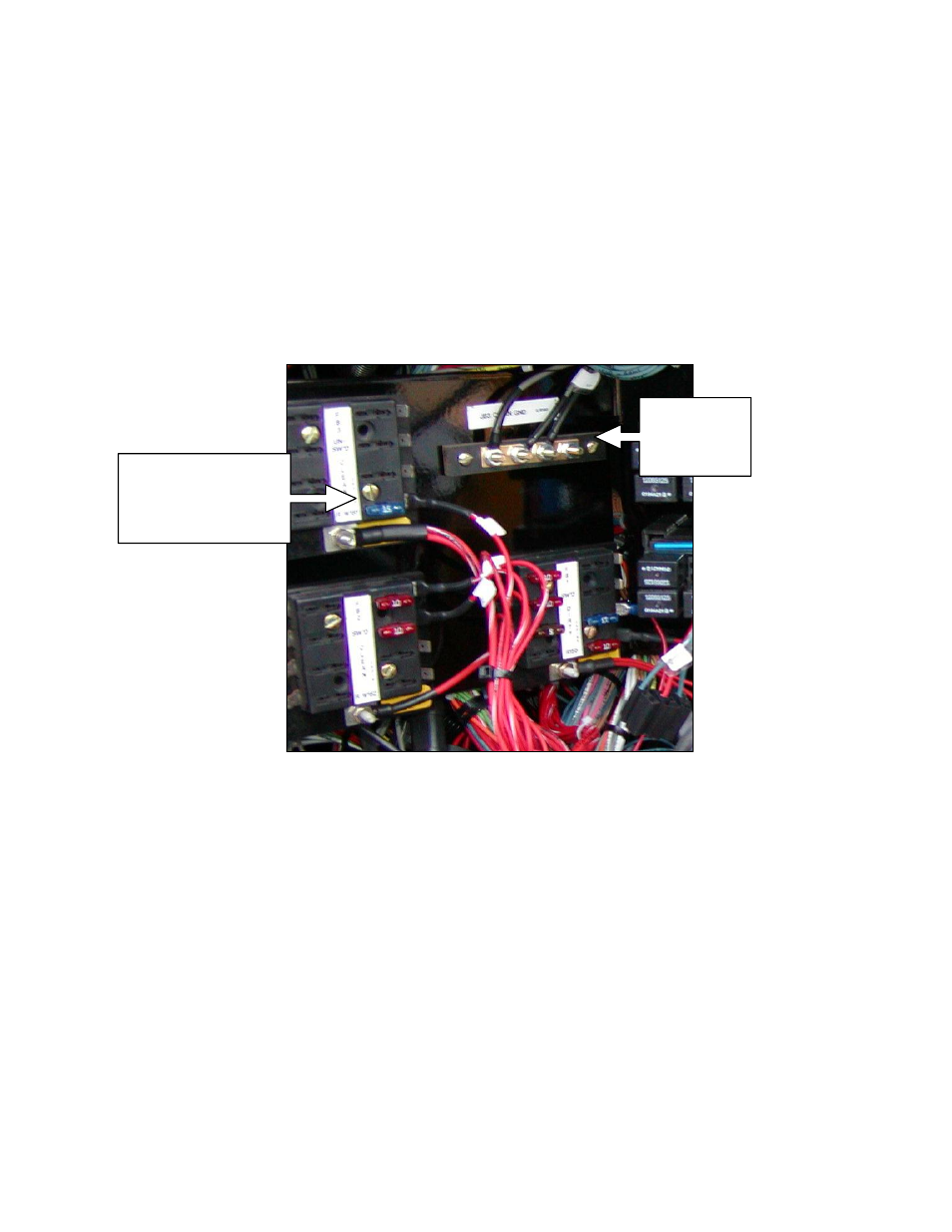
5. There is an access hole to the sprayer
electrical panel on the front right
corner. Route the free end of C14 to
the electrical panel through this hole.
6. In the electrical panel towards the front
of the sprayer, wire the white wire on
C14 to +12V and the black wire to
Ground. Each polarity is labeled on the
wire. Refer to for Figure 27
recommended +12V and Ground
connections inside of the electrical
panel.
7. Install the provided 15A automotive
fuse into the slot beside the +12V
power connection.
Figure 27: Power and Ground Connections
8. Route R16 of C10 to the exterior of
the cab. There is an access panel located
on the front right corner of the cab
floor. It can be removed to allow cables
to be routed to the exterior of the cab.
Use this panel to route R16 through
the hole of the provided access panel kit
(B16) (Figure 28). B16 maintains the
cab seal. Leave the cover plates
unscrewed at this point. Figure 29
shows the access panel and the installed
plates.
9. Connect the 16-pin AMP plug (P16) of
the valve extension cable (C11) to the
free end (R16) of C10 on the outside
of the cab (Figure 26).
Connect
GROUND
wire here
Connect +12V wire
(spade terminal)
here and install 15A
fuse