3 hydraulic plumbing – NORAC UC4+BC+RG4 User Manual
Page 23
20
4.6.3 Hydraulic Plumbing
WARNING!
From this point in the installation the
booms will be inoperative until the
electronics are fully installed.
1. After the NORAC valves are mounted,
the hydraulic hoses and fittings can be
plumbed. The plumbing for the hydraulic
circuit is shown schematically in Figure
3.
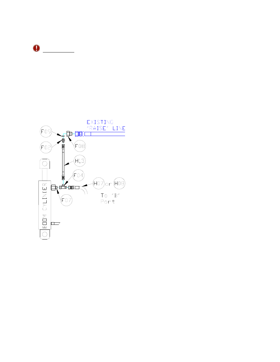
Figure 23: Boom Cylinder “Raise”
Line Fittings
2. The “raise” lines from the side of the
cylinders, which raise the booms, must
be connected to the “B” ports of the
NORAC valve block. Disconnect the
existing 3/4" “raise” lines on the boom
cylinder end. Install F08, F09, F02 and
H13 onto the disconnected hose end
(Figure 23).
3. Install F07 and F04 onto the cylinder
and run the provided hoses H7 and H8
(Figure 23). The longer hose H8 must
be installed on the side of the sprayer
opposite the valve block.
4. Tee the free end of H13 in to the open
port on F04.
5. Route H7 and H8 to the NORAC valve
block. Connect to the “B” ports. Follow
the existing 3/4" lines to the valve. (Do
NOT disconnect the 3/4" lines from the
Rogator valve block.)
6. Install F12 between the tank port and
the existing tank line (Figure 24).
7. Tee H5 in to the open port on F12
using F13 (Figure 24).
8. Install F05 between the pressure port
and the existing pressure line with F11
(Figure 24).
9. Tee H4 in to the open port on F05
using F14 (Figure 24).
10. Route hoses H4 and H5 from the
tee(s) to the NORAC valve block to
supply pressure and tank respectively.