NORAC UC4+BC+RG6 User Manual
Page 30
27
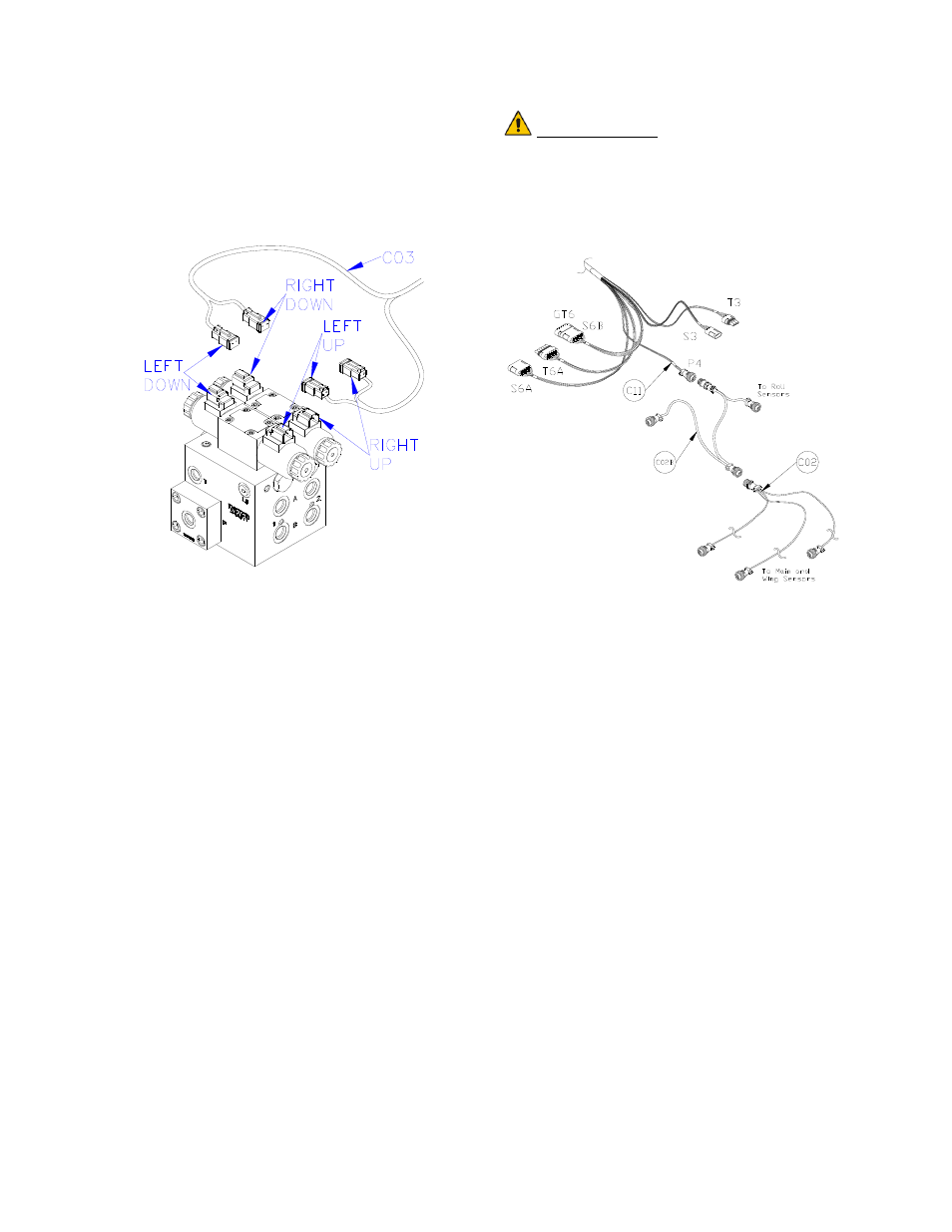
14. The connectors on the valve cable
(C03) are marked RIGHT UP, LEFT
UP, RIGHT DOWN and LEFT
DOWN. Cables labeled with UP go
on the same side as the hydraulic hoses.
Figure 30: Valve Cable Connections
15. Connect the CAN Node cable (C02B)
to the 4-pin AMP plug on C11 (Figure
31).
16. Route the CAN Node cable (C02B) to
the roll sensors which are installed in
Section 4.5. Follow existing cables
and/or hydraulic lines.
17. Connect the 4-pin AMP connectors to
the roll sensors.
18. Connect the sensor branch cable (C02)
to the 4-pin AMP plug on C02B
(Figure 31).
19. Route the sensor branch cable (C02) to
the wing and main sensors and connect
to the sensors. Follow existing cables
and/or hydraulic lines along the boom.
20. Cable-tie the installed cables every 12
inches.
IMPORTANT:
Provide enough slack in all cables to
account for the movement of the
main section, parallel lift, and
FOLDING boom movement.
Figure 31: Cable Configurations: C11,
C02 and C02B