NORAC UC4+BC+FC1 User Manual
Page 24
21
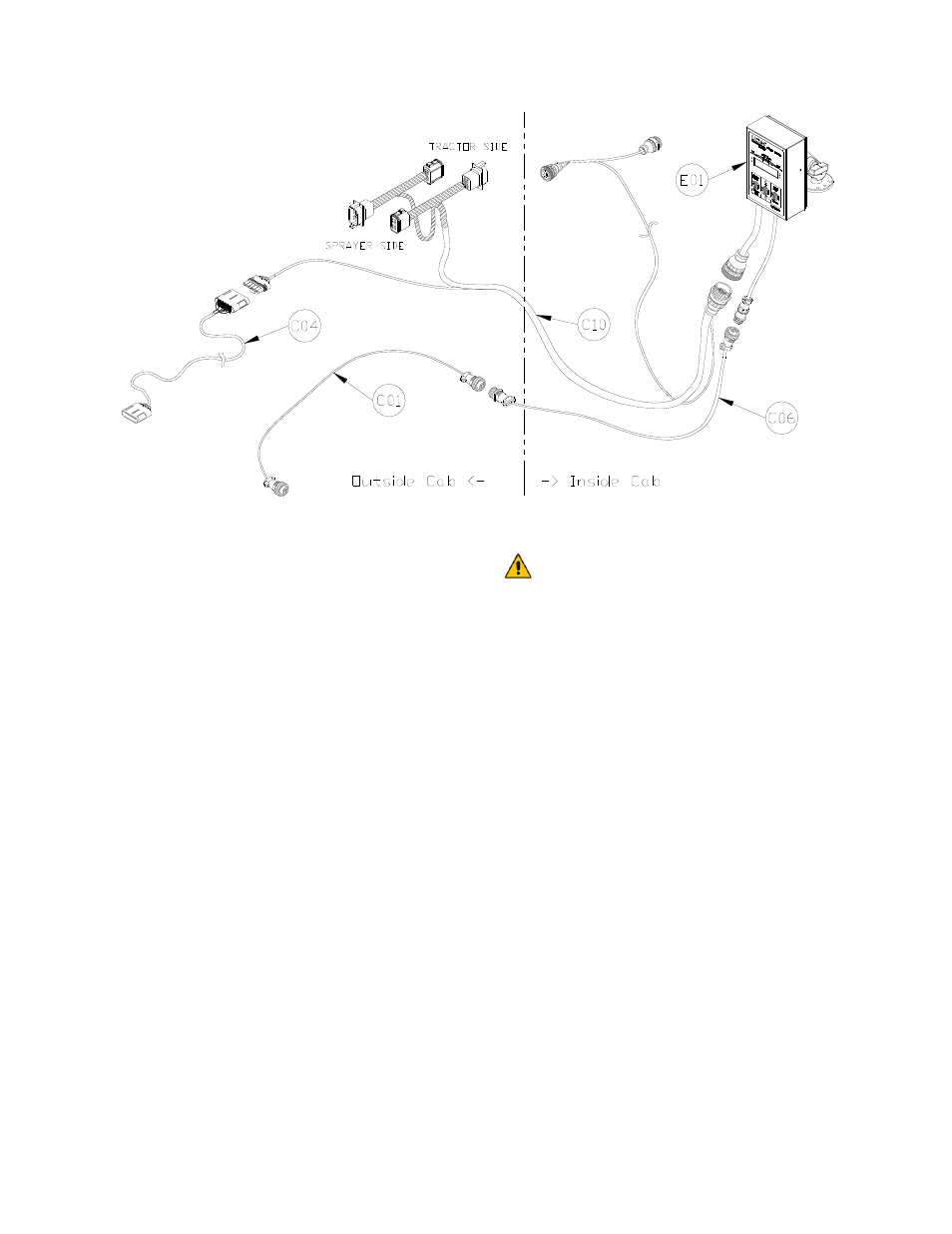
Figure 25: Cable Configurations: C01, C06, C04, and C10
2. Connect the 16-pin AMP plug on the
UC4 power cable (C10) to the UC4
Control Panel (E01) in the tractor cab.
The 3-pin AMP plug tee on C10 is
connected between the power cable
from the sprayer and the tractor power
outlet (Figure 25).
3. Connect 4-pin AMP plug on the sensor
extension cable (C06) to E01. Route
C10 and C06 to the tractor hitch.
4. Connect two sets of tees on C10 in-
line with the Flexi-Coil joystick cable at
the hitch connections. One of the
receptacles on the tees should be
marked Sprayer. This connector is to
be connected to the Flexi-Coil plug
that comes from the sprayer side. Plug
the other connections together.
5. Connect the valve extension cable
(C04) to the 6-pin Tower on C10.
The valve extension cable (C04)
may be packaged with one GP
end not installed. This is normal;
it helps installations for other
sprayer types. Pin this connector
on (connector included) as per
drawing in Section 5.5. TAKE
EXTRA CARE! These pins
require a special tool to remove
them if you make an error.
6. Connect the sensor trunk cable (C01)
to 4-pin AMP receptacle on C06 at the
hitch.
7. Route C04 and C01 from the hitch to
the rear of the sprayer to the area
where the NORAC hydraulic valves are
located.
8. Connect the 6-pin Tower on the Valve
Cable (C03) to the 6-pin Shroud on
C04 at the rear of the sprayer (Figure
27).