8 completing the installation – NORAC UC4+BC+AP2 User Manual
Page 25
22
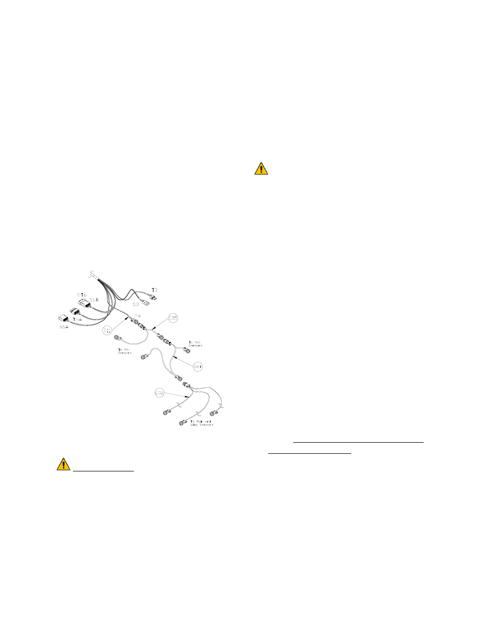
16. Route the sensor roll bias cable (C05)
to the chassis roll sensor. Follow
existing cables and/or hydraulic lines.
17. Route the CAN Node cable (C02B) to
the roll sensors. Follow existing cables
and/or hydraulic lines.
18. Connect the sensor branch cable (C02)
to the 4-pin AMP plug on C02B
(Figure 26).
19. Route the sensor branch cable (C02) to
the wing and main sensors. Follow
existing cables and/or hydraulic lines
along the boom.
20. Cable-tie the installed cables every 12
inches.
Figure 26: Cable Configurations: C11,
C02, C02B and C05
IMPORTANT:
Provide enough slack in all cables to
account for the movement of the
main section, parallel lift, and
FOLDING boom movement.
4.8 C
OMPLETING THE
I
NSTALLATION
1. Start up your sprayer and test the
sprayer’s functionality. The NORAC
Control Panel does not need to be
powered up for the original switches to
function. Unfold the booms and
raise/lower each boom and main
section.
Confirm that the cabling/hoses
are agreeable to the entire range
of motion.
2. If any functions do not work, review the
hydraulic and electrical portions of this
manual to check for proper installation.
If you still have trouble, contact
NORAC for assistance.
3. Turn on the power for the UC4+
Control Panel using the switch on the
side of its chassis.
4. Repeat the Boom Speed Test as
described in Section 4.2 Boom Speed
Test with the NORAC UC4+ Spray
Height Control system installed.
Record the results for comparison in
Table 5.
5. The procedure for the installation of the
UC4+ Spray Height Control system is
now complete. Begin the AUTOMATIC
SYSTEM SETUP procedure as described
in the UC4+ Sprayer Boom Control
Operator’s Manual (M01).