3 wing sensor installation – NORAC UC4+BC+AP2 User Manual
Page 12
9
4.3 W
ING
S
ENSOR
I
NSTALLATION
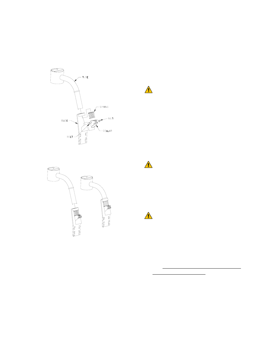
1. Assemble the Breakaway Sensor
Mounting Brackets (B11) as show in
Figure 4 and Figure 5.
Figure 4: Breakaway Sensor Bracket
Exploded View
Figure 5: Breakaway Sensor Mounting
Bracket Assembly
To assemble the breakaway sensor
bracket:
a) Assemble the bolt and nut into the
collar.
b) Grease the bottom edge of the
collar and the angled tube of the
base.
c) Place the collar onto the angled tube
of the mounting base.
d) Install the spring between the collar
and the upper ring of the base.
e) Insert tube through assembly and
tighten the collar
2. Mount the sensor bracket onto the
boom.
If possible, mount the sensor
brackets while the booms are in
their folded position to ensure
that they will not interfere with
anything when the boom is folded
for transport.
3. The sensor mounting brackets can be
installed with the mounting base behind
(Figure 8) or in front of the tube
(Figure 6).
Mounting the sensor bracket to
the break-away section of the
boom may cause the boom to
drop suddenly as a break-away
occurs. This will occur on break-
away sections which lift as they
break away.
For optimal boom tip protection,
it is recommended that the
sensor be mounted within
approximately two feet (60cm) of
the boom tip.
Please refer to the UC4+ Spray Height
Control system warranty at the end of
the UC4+ Sprayer Boom Control
Operator’s Manual (M01) for
implications.
4. Mount the NORAC UC4+ ultrasonic
sensor (E02) into the sensor brackets.
The sensors should be oriented forward
(ahead) of the boom (see Figure 6 and
Figure 8).