Procedure – Maxim Integrated MAXREFDES71 ZedBoard User Manual
Page 10
MAXREFDES71# ZedBoard Quick Start Guide
10
6. Procedure
1. Install a 2-pin header on the J18 connector on the ZedBoard if the 3V3 header is
missing.
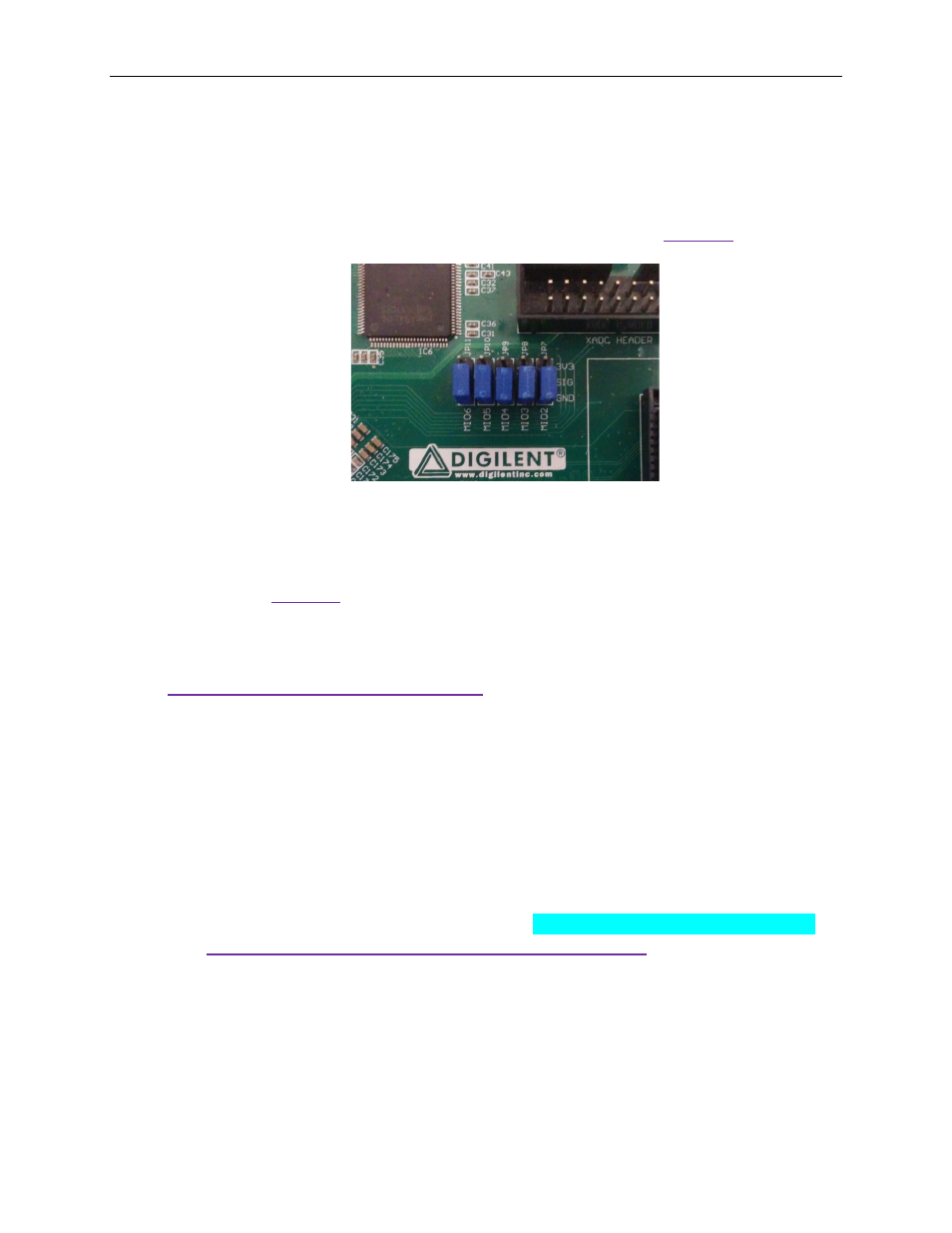
2. Configure the ZedBoard boot source jumpers as shown in
the shunt on JP6.
Figure 8 JTAG Mode Jumper Settings
3. Remove any shunt on 1V8 and 2V5 headers, and install a shunt on the 3V3
header.
4. Connect the MAXREFDES71# board to the J1 FMC connector of the ZedBoard
as shown in
5. Power up the ZedBoard by sliding the SW8 switch on the ZedBoard to the ON
position.
6. Download the latest RD71V01_00.ZIP file at
All files available for download are
available at the bottom of the page.
7. Extract the RD71V01_00.ZIP file to a directory on your PC. The location is
arbitrary but the maximum path length limitation in Windows (260 characters)
should not be exceeded.
In addition, the Xilinx tools require the path to not contain any spaces.
C:\Do Not Use Spaces In The Path\RD71V01_00.ZIP
(This path has spaces.)
For the purposes of this document, it will be C:\designs\maxim\RD71V01_00\.
See
Appendix A: Project Structure and Key Filenames
the project structure and key filenames.