Make Noise RxMx User Manual
Page 7
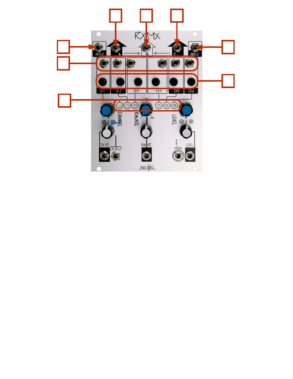
RxMx Panel Controls
1. Out A: 10Vpp (depending upon Level setting and source material), DC coupled output for CH. 1, CH. 2
and Aux A. Normalled to Out B.
2. Out B: 10Vpp (depending upon Level setting and source material), DC coupled output for CH. 3, CH. 4
additionally Out A and Out C are Normalled to this output.
3. Out C: 10Vpp (depending upon Level setting and source material), DC coupled output for CH. 5, CH. 6 and
Aux C. Normalled to Out B.
4. Aux A: Direct coupled signal input to the Out A sum circuit. Capable of accepting audio or control signals.
Also allows for the chaining of multiple RxMx, Optimix and modDemix units to create larger mixes.
Typical input range of 10Vpp.
5. Aux C: Direct coupled signal input to the Out C sum circuit. Capable of accepting audio or control signals.
Also allows for the chaining of multiple RxMx, Optimix and modDemix units to create larger mixes.
Typical input range of 10Vpp.
6. INputs for CH. 1, CH. 2, CH. 3, CH. 4, CH. 5 and CH. 6: Direct coupled signal input capable of accepting
audio or control signals. Normalized to Expansion header for use with DPO or FXDf. Typical input
range of 10Vpp.
7. Input Attenuators for CH. 1, CH. 2, CH. 3, CH. 4, CH. 5 and CH. 6: Sets input level for associated channel
input. This attenuator is before the LPG circuit.
8. Channel Drive Indicators 1, 2, 3, 4, 5, 6: LEDs to indicate which of the 6 LPG circuits are currently selected
and being driven by the LEVEL and STRIKE parameters.
1
2
4
5
3
6
7
8