1 heater placement, 2 installation of indoor heaters – LAARS Mighty Therm LO-NOx PW (Sizes 500-1825) - Install and Operating Manual User Manual
Page 4
LAARS HEATING SYSTEMS
Page 4
SECTION 2.
Installation
2.1 Heater Placement
The heater must be placed to provide specific
clearances on all sides for maintenance and
inspections. There must also be minimum distances
maintained from combustible surfaces. These
clearances also apply to noncombustible materials
because the heater requires air circulation for proper
operation.
The heater should be mounted on a level surface.
An integral base for an installation on combustible
flooring is provided as standard equipment on all
models.
Do not install a heater on carpeting.
Under the national Fuel Gas Code, ANSI
Z223.1, it is permissible to place the heater on floors
other than noncombustible when the installation
complies with the American Insurance Code. Figures
2, 3, and 4 show common installation on combustible
flooring.
2.2 Installation of Indoor Heaters
Locate the heater to provide adequate clearance
for inspection and service on all sides. See Table 1.
Install indoor heaters on a waterproof floor with
an adequate floor drain and a 6" (152mm) minimum
curb on all four sides to protect the building if heater
repairs are required. The manufacturer will not be
held liable for any water damage in connection
with this heater.
2.2.1 Combustion Air Supply
The heater location must provide sufficient air
supply for proper combustion and ventilation of the
surrounding area as outlined in the latest edition of
ANSI standard Z223.1, and any local codes that may
be applicable. Inadequate combustion air supply may
result in incomplete combustion, sooting of the heat
exchanger, and unsafe operation of the boiler.
2.2.1.a Conventional Ventilation
In the United States, the most common
requirements specify that the space shall communicate
with the outdoors in accordance with method 1 or 2,
which follow. Where ducts are used, they shall be of
the same cross-sectional area as the free area of the
openings to which they connect.
Method 1: Two permanent openings, one
commencing within 12 inches (300 mm) of the top
and one commencing within 12 inches (300 mm) of
the bottom, of the enclosure shall be provided. The
openings shall communicate directly, or by ducts, with
the outdoors or spaces that freely communicate with
the outdoors.. When directly communicating with the
outdoors, or when communicating to the outdoors
through vertical ducts, each opening shall have a
minimum free area of 1 square inch per 4000 BTU/h
(550 square mm/kW) of the total input rating of all
equipment in the enclosure. When communicating to
the outdoors through horizontal ducts, each opening
shall have a minimum free area of not less than 1
square inch per 2000 BTU/h (1100 square mm/Kw) of
the total input rating of all equipment in the enclosure.
Clearance
Indoor
Outdoor
from
in.
mm
in.
mm
Top
30
762
unobstructed
Water Conn. side
12*
305
24
610
Pump side
6*
152
24
610
Front
Alcove*
unobstructed
Rear
8
203
24
610
Vent pipe**
6
152
- - -
Hot water pipes
per code
per code
* Water connection and pump side clearances of 24" (610mm)
and front clearances of 48" (1219mm) will allow easier
service access.
** One inch using type B vent (refer to Manufacturer's Instructions).
Table 1. Minimum Heater Clearances From
Adjacent Surfaces.
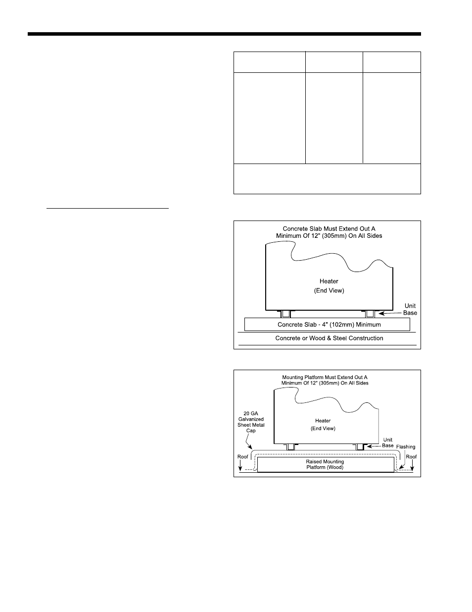
Figure 2. Typical Heater Installation on Concrete Slab.
Figure 3. Typical Heater Installation on Roof Using
Raised Platform (wood).