3i. direct vent balanced flue system – LAARS MAX 165 (DV) - Installation, Operation and Maintenance Instructions User Manual
Page 8
Page 8
LAARS Heating Systems
3I. Direct Vent Balanced Flue System
With this system flue gases are vented directly
through the wall and fresh air for combustion is drawn
in through the same terminal, thus ensuring wind
pressures are equal to the intake and flue gas
discharge to create a balanced flue condition.
The terminal also incorporates a silencer to
reduce the flue gas discharge noise and a specially
designed end cap which throws the flue gases clear of
the wall to avoid surface discoloration.
NOTE: If the burner is not correctly adjusted it
is possible that surface discoloration may occur. Laars
will not accept any responsibility for such
discoloration.
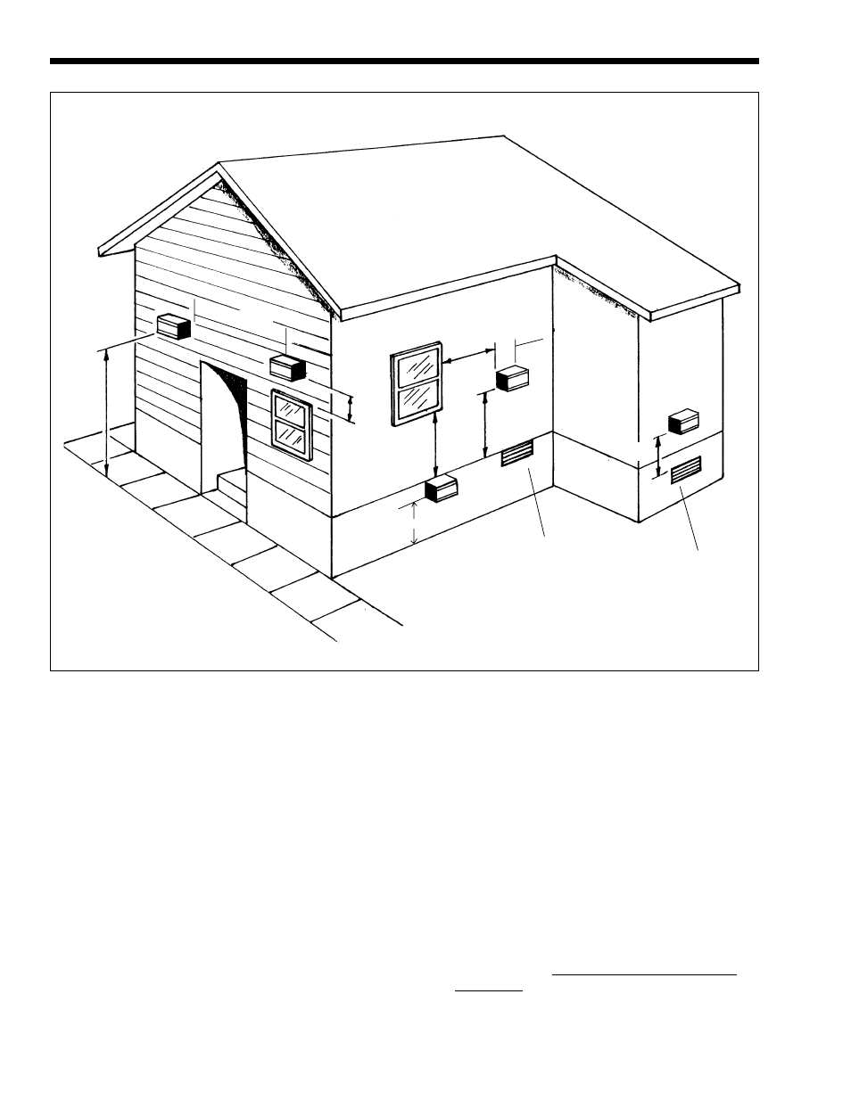
The position chosen for the Balanced Flue
Terminal must conform to the following guidelines:
1.
The terminal shall not be less than 3 ft. (0.9m)
above or 10 ft. (3m) horizontally from any forced
air inlet into the building.
2.
The terminal shall not be less than 4 ft. (1.2m)
below, 4 ft. (1.2m) horizontally or 1 ft. (0.3m)
above any door, window, or gravity air inlet into
the building.
3.
The terminal shall not be less than 3 ft. (0.9m)
from an inside corner of an L shaped building.
4.
The terminal shall not be less than 7 ft. (2.1m)
above grade when located adjacent to public
walkways.
5.
The terminal shall not be less than 2 ft. (0.6m)
from an adjacent building.
6.
IMPORTANT: The terminal shall be located at
a height not liable to blockage from leaves, snow
or other debris, at least one foot (0.3m) above
grade level.
7.
The terminal shall be positioned so that flue gases
are not directed where they can jeopardize people,
overheat combustible structures, or enter buildings.
Forced Air Inlet
Gravity Air Inlet
1
(0.3)
4
(1.2)
4
(1.2)
3
(0.9)
3
(0.9)
³
³
1.5
(0.5)
7
(2.1)
Minimum 1.5
(0.5)
³
³
Figure 4. Terminal Locations - Minimum Distances.
1
(0.3)
Dimensions shown in feet (m).
1 (0.3)