3 unpacking the appliance, 4 locating the appliance, 5 clearances – LAARS EDN Series - Installation, Operation and Maintenance Instructions User Manual
Page 4: Laars heating systems company
Page 4
LAARS Heating Systems Company
Options Code
X = None
Revision
2 = Second
Revision
b. The Canadian Electrical Code (CSA C22.1),
latest edition.
c. All applicable local installation codes must also
be adhered to.
All vent installations must be made in accordance
with:
a. The applicable venting requirements of the
National Fuel Gas Code (ANSI Z223.1/NFPA
54), latest edition; or
b. in Canada, The Natural Gas and Propane
Installation Code (CSA B149.1), latest edition.
All applicable provisions of local building codes
should also be adhered to.
1.3 Unpacking the Appliance
Remove all packing and tie down materials.
Make immediate claims (to the carrier) if the appliance
and its packaging are damaged.
1.4 Locating the Appliance
The appliance is designed for installation on
combustible flooring, in alcoves, basements, closets,
or utility rooms. It must NOT be installed on
carpeting. IF INSTALLED IN A FINISHED AREA,
PROVISION SHOULD BE MADE FOR DRAINAGE
OF ANY ACCIDENTAL SPILLAGE OR LEAKAGE.
The location for the unit should be chosen with
regard to venting dimensions, convenient access to
piping, and accessibility for service and cleaning.
The boiler shall be installed so that the gas
ignition system components are protected from water
(dripping, spraying, rain, etc.) during appliance
operation or service (circulator replacement, control
replacement, etc.).
1.5 Clearances
The dimension and criteria in Table 1 should be
followed when choosing the location for the unit.
SECTION 2.
Venting Options
The Endurance boilers are certified as direct vent,
sealed combustion boilers, when vented using one of
the following two methods:
1) Concentric direct vent, which has a flue gas pipe
inside a combustion air pipe.
2) Non-concentric direct vent, using separate pipes
for the flue gases and the combustion air.
The Endurance boilers can also take air from
the space (when properly sized), and be vented as a
Category IV appliance.
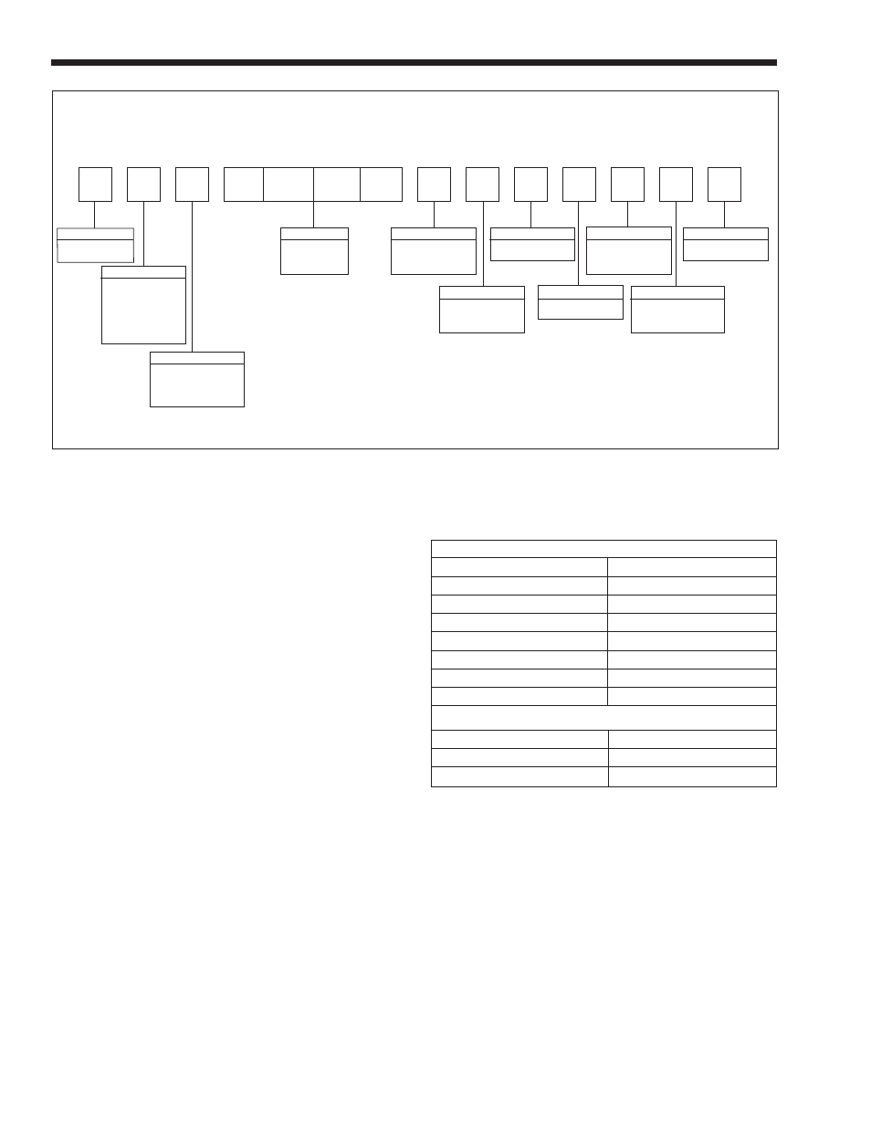
Figure 3. Model Structure.
1
2
3
4
5
6
7
8
9
10
11
12
13
14
E
I
F
2
X
Prod. Line
E = Endurance
Usage
B = Combination,
Heating &
Domestic
Water
D = Heating Only
Type
P = Standard
N = Non Ferrous
(ED Units Only)
BTU Input
0 1 1 0
0 1 7 5
Fuel
N = Natural Gas
P = Propane
Altitude
A = 0' - 5,000'
H = Over 5,000'
Location
I = Indoor
Firing Mode
F = Modulating
Country of Sale
A = USA & Canada
R = Russia
Minimum Clearances From Combustible Materials
Back
1 inch
25mm
Left Side
1 inch
25mm
Right Side
1 inch
25mm
Front
1 inch
25mm
Top (Alcove Install)
1 inch
25mm
Top (Closet Install)*
22 inches 559mm
Vent: Concentric, Direct
0 inch
0mm
Vent: Category
3 inches 76mm
Suggested Serviceability Clearances
Front
18 inches 457mm
Left Side
6 inches 152mm
Right Side
6 inches 152mm
*Minimum closet height 6'9" 206 cm
Table 1. Clearances.