LAARS Pennant PNCV - Install and Operating Manual User Manual
Page 14
LAARS Heating Systems
Page 14
SECTION 3.
Gas Supply and Piping
3.1 Gas Supply and Piping
Gas piping should be supported by suitable
hangers or floor stands, not by the appliance.
The Pennant’s gas train allows the user to pipe
the gas from either the right side or the left side of
the unit. As shipped, the right side of the gas train is
capped off, and there is a manual valve on the left side.
If desired, the manual valve on the left side of the gas
train may be moved to the right side, and the cap on
the right side may be moved to the left.
Review the following instructions before
proceeding with the installation.
1. Verify that the appliance is fitted for the proper
type of gas by checking the rating plate. Pennant
appliances are equipped to operate at elevations
up to 10,000 feet (3050m). Pennant appliances
may be adjusted to operate properly at altitudes
above 2500 feet (
see Section 6.5.2
) and the input
will be reduced if the heating value of the gas
supply is below sea level values.
2. The maximum inlet gas pressure must not
exceed 13" w.c. (3.2kPa). The minimum inlet gas
pressure is 5 in. w.c. (1.2 kPa).
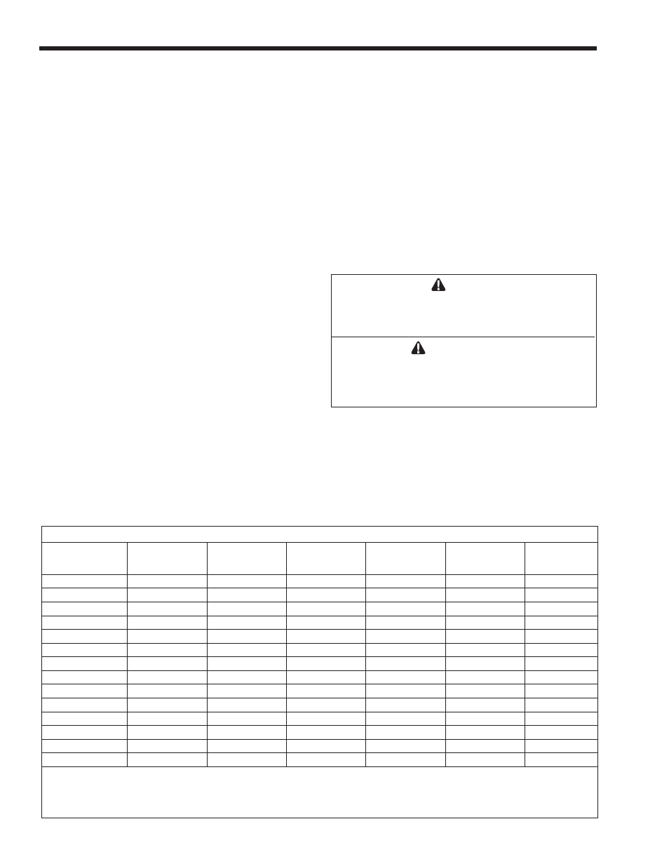
3. Refer to
Table 7
, size supply.
4. Run gas supply line in accordance with all
applicable codes.
5. Locate and install manual shutoff valves in
accordance with state and local requirements.
6. A sediment trap must be provided upstream of
the gas controls.
7. All threaded joints should be coated with
piping compound resistant to action of liquefied
petroleum gas.
8. The appliance and its individual shutoff valve
must be disconnected from the gas supply piping
during any pressure testing of that system at test
pressures in excess of 0.5 psig (3.45 kpa).
9. The unit must be isolated from the gas supply
system by closing its individual manual shutoff
valve during any pressure testing of the gas
supply piping system at test pressures equal to or
less than 0.5 psig (3.45 kpa).
10. The appliance and its gas connection must be
leak tested before placing it in operation.
11. Purge all air from gas lines.
WARNING
Do not use open flame to check for leaks. An open
flame could lead to explosion, which could result in
property damage, serious injury or death.
AVERTISSEMENT
Ne recherchez pas les fuites avec une flamme nue.
Une flamme nue peut provoquer une explosion qui
peut causer des dommages matériels, de sérieuses
blessures corporelles ou la mort.
NOTE: The Pennant appliance and all other gas
appliances sharing the gas supply line must be firing
at maximum capacity to properly measure the inlet
supply pressure. The pressure can be measured at
the supply pressure port on the gas valve. Low gas
pressure could be an indication of an undersized
gas meter, undersized gas supply lines and/or an
obstructed gas supply line.
Distance from Gas Meter or Last Stage Regulator
Size and
Gas Type
0-100'
0-31 m
100-200'
31-61m
200-300'
61-91m
500 natural
1½"
3.8 cm
2"
5.1 cm
2"
5.1 cm
500 propane
1"
2.5 cm
1½"
3.8 cm
1½"
3.8 cm
750 natural
2"
5.1 cm
2"
5.1 cm
2½"
6.4 cm
750 propane
1½"
3.8 cm
1½"
3.8 cm
2"
5.1 cm
1000 natural
2"
5.1 cm
2½"
6.4 cm
3"
7.6 cm
1000 propane
1½"
3.8 cm
2"
5.1 cm
2½"
6.4 cm
1250 natural
2½"
6.4 cm
2½"
6.4 cm
3"
7.6 cm
1250 propane
2"
5.1 cm
2"
5.1 cm
2½"
6.4 cm
1500 natural
2½"
6.4 cm
3"
7.6 cm
3"
7.6 cm
1500 propane
2"
5.1 cm
2½"
6.4 cm
2½"
6.4 cm
1750 natural
2½"
6.4 cm
3"
7.6 cm
3"
7.6 cm
1750 propane
2"
5.1 cm
2½"
6.4 cm
2½"
6.4 cm
2000 natural
3"
7.6 cm
3"
7.6 cm
3½"
8.9 cm
2000 propane
2½"
6.4 cm
2½"
6.4 cm
3"
7.6 cm
Notes:
1. These figures are based on 1/2" (0.12 kPa) water column pressure drop.
2. Check supply pressure and local code requirements before proceeding with work.
3. Pipe fittings must be considered when determining gas pipe sizing.
Table 7. Gas Piping Size.