LAARS Mighty Therm2 MT2P (Sizes 500–2000 MBTU/h) - Install and Operating Manual User Manual
Page 6
LAARS Heating Systems
Page 6
SECTION 2.
Venting and Combustion Air
2.1 Combustion Air
MT2P pool heaters must have provisions for
combustion and ventilation air in accordance with
Section 5.3, Air for Combustion and Ventilation, of the
National Fuel Gas Code, ANSI Z223.1, or Sections 7.2,
7.3 or 7.4 of CAN/CGA B149, Installation Codes, or
applicable provisions of the local building codes.
A MT2P appliance may receive combustion air
from the space in which it is installed, or it can be
ducted directly to the unit from the outside. Ventilation
air must be provided in either case. Never obtain
combustion air from the pool area. Corrosion of and/or
damage to the pool heater may result.
2.1.1 Combustion Air From Room
In the United States, the most common
requirements specify that the space shall communicate
with the outdoors in accordance with method 1 or 2,
which follow. Where ducts are used, they shall be of
the same cross-sectional area as the free area of the
openings to which they connect.
Method 1: Two permanent openings, one
commencing within 12 inches (30 cm) of the top
and one commencing within 12 inches (30 cm) of
the bottom, of the enclosure shall be provided. The
openings shall communicate directly, or by ducts,
with the outdoors or spaces that freely communicate
with the outdoors. When directly communicating
with the outdoors, or when communicating to the
outdoors through vertical ducts, each opening shall
have a minimum free area of 1 square inch per 4000
Btu/hr (5.5 square cm/kW) of total input rating of
all equipment in the enclosure (
see Table 3
). When
communicating to the outdoors through horizontal
ducts, each opening shall have a minimum free area of
not less than 1 square inch per 2000 Btu/hr (11 square
cm/kW) of total input rating of all equipment in the
enclosure.
Table 3
shows data for this sizing method,
for each MT2P model.
Method 2: One permanent opening, commencing
within 12 inches (30 cm) of the top of the enclosure,
shall be permitted. The opening shall directly
communicate with the outdoors or shall communicate
through a vertical or horizontal duct to the outdoors or
spaces that directly communicate with the outdoors and
shall have a minimum free area of 1 square inch per
3000 Btu/hr (7 square cm/kW) of the total input rating
of all equipment located in the enclosure. This opening
must not be less than the sum of the areas of all vent
connectors in the confined space.
Other methods of introducing combustion and
ventilation air are acceptable, providing they conform
to the requirements in the applicable codes listed above.
In Canada, consult local building and safety codes
or, in absence of such requirements, follow CAN/CGA
B149.
2.1.2 Intake Combustion Air
Never obtain combustion air from the pool area.
Corrosion of and/or damage to the pool heater may
result. The combustion air can be taken through the
wall, or through the roof. When taken from the wall, it
must be taken from out-of-doors by means of the Laars
horizontal wall terminal (
see Table 1
). When taken
from the roof, a field-supplied rain cap or an elbow
arrangement must be used to prevent entry of rain water
(
see Figure 2
).
Use single-wall galvanized pipe (
per Table
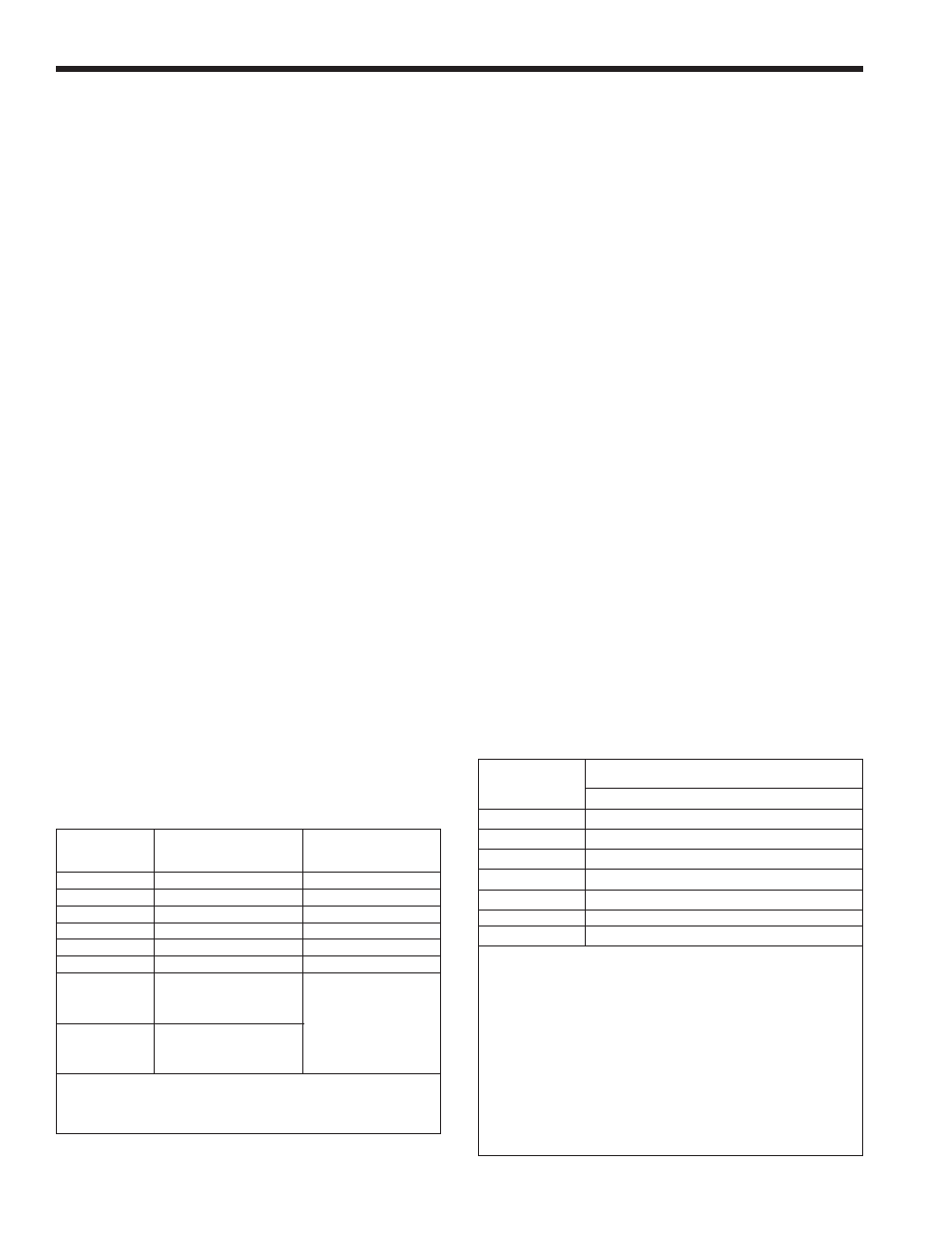
EACH OPENING*
SIZE
Square inches
Square cm
500
125
807
750
188
1213
1000
250
1613
1250
313
2020
1500
375
2420
1750
438
2826
2000
500
3226
*Net Free Area in Square Inches / Square cm
Area indicated is for one of two openings; one at floor level
and one at the ceiling, so the total net free area could be
double the figures indicated.
This chart is for use when communicating directly with the
outdoors. For special conditions and alternate methods,
refer to the latest edition of ANSI Z223.1.
Note: Check with louver manufacturers for net free area of
louvers. Correct for screen resistance to the net free area
if a screen is installed. Check all local codes applicable to
combustion air.
Table 3. Combustion Air Openings.
REqUIRED
RECOMMENDED
APPLIANCE
CLEARANCE FROM
SERVICE ACCESS
SURFACE
COMBUSTIBLE MATERIAL
CLEARANCE
inches
cm inches
cm
Left Side
1
2.5 24
61
Right Side
1
2.5 24
61
Top
1 2.5 12 30
Back
1
2.5
**
12**
30**
Front
1
2.5 36
91
Vertical
(Category 1)
6*
15.2*
Vent
Horizontal
per UL1738 venting
(Category 3)
system supplier’s
Vent
instructions
*1" (2.5cm) when b-vent is used.
**When vent and/or combustion air connects to the back,
recommended clearance is 36" (91cm).
Table 2. Clearances.