2 temperature (operating) control, 3 limit controls, Laars heating systems – LAARS Mighty Therm2 MT2P (Sizes 500–2000 MBTU/h) - Install and Operating Manual User Manual
Page 14: Page 14
LAARS Heating Systems
Page 14
35 67
T'stat
35 67
T'stat
35 67
T'stat
35 67
T'stat
AQUASTAT
STAGE 1
STAGE 1
SWITCH
SELECT
PUMP
L1
TB1-1
HEATER
HIGH
LIMIT
POLE 6
POLE 5
TERMINAL
BLOCK 1
BD #2
IGN
BD #1
IGN
IGN
BD #2
IGN
IGN
BD #1
IGN
BD #1
IGN
BD #2
IGN
BD #2
IGN
BD #1
IGN
LIGHT
10
GAS
HIGH
GAS
8
2
PUMP
IGN
BD #1
IGN
BD #2
IGN BD #2
BD #1
IGN
DRY CONTACT
ALARM
ALARM
SILENCE
BELL
IGN BD #2
L.O.
L.O.(G)
L.O.
BD #1
IGN
L.O.(G)
1
P2
P1
1
2
Delay on Break
Relay
Initiate
9
stage 2
stage 1
Gas Valve
Gas Valve
IGN
BD #1
IGN
BD #2
6
Press
35 67
Press
35 67
#2
of Fan
Proof
of Fan
#1
4
3
Interlock
Field
Gas
35 67
Gas
35 67
IGN
BD #2
IGN
BD #1
IGN
BD #1
BD #2
IGN
24V
35 67
24V
35 67
GND
35 67
GND
35 67
BLOCK
POOL
SUPPY
HIGH
LIMIT
LOW
24 VAC
120 VAC
BLOWER 2
BLOWER 1
LOW
HIGH
LOW
HIGH
K1
K2
K1
K2
F2
35 67
F2
35 67
F1
35 67
F1
35 67
K3
HSI #2
HSI #1
120 VAC
DPDT
MAIN
POWER
SWITCH
S2
S2
35 67
35 67
L2
35 67
L2
35 67
BD #1
IGN
S1
S1
35 67
35 67
35 67
L1
35 67
JUMPER
N1
FLOW
SWITCH
5
SWITCH
SELECT
PUMP
L1
TB1-1
POLE 6
POLE 5
TERMINAL
BLOCK 1
BD #2
IGN
BD #1
IGN
BD #1
IGN
BD #2
IGN
BD #2
IGN
BD #1
IGN
BD #1
IGN
BD #2
IGN
BD #2
IGN
BD #1
IGN
LIGHT
FLUE
PUMP
IGN
BD #1
IGN
BD #2
DRY CONTACT
ALARM
R
LIGHT
ALARM
SILENCE
BELL
35 67
35 67
35 67
35 67
1
P2
P1
1
2
K2
K1
Delay on Break
Relay
Initiate
K3
9
7
stage 2
stage 1
Gas Valve
Gas Valve
IGN
BD #1
IGN
BD #2
6
Press
35 67
Press
35 67
#2
of Fan
Proof
Proof
4
3
Interlock
Field
Gas
35 67
Gas
35 67
IGN
BD #2
IGN
BD #1
IGN
BD #1
BD #2
IGN
24V
35 67
24V
35 67
GND
35 67
GND
35 67
24 VAC
120 VAC
BLOWER 2
BLOWER 1
LOW
HIGH
LOW
HIGH
K1
K2
K1
K2
F2
35 67
F2
35 67
F1
35 67
F1
35 67
K3
HSI #2
HSI #1
120 VAC
DPDT
MAIN
POWER
SWITCH
S2
S2
35 67
35 67
L2
35 67
L2
35 67
BD #2
IGN
BD #1
IGN
S1
S1
35 67
35 67
35 67
L1
35 67
JUMPER
N1
L1
STAGE 2
24V
C
H2331200E
5.1.1 Changing Single Circuit to Two
Circuits
Sizes 500 to 1500 will be shipped from the factory
for a single 120-volt power supply. To use a separate
circuit for the pump:
1. Ensure power is disabled to the unit
2. Remove the three jumper wires that connect
the L2, N2 and GROUND wires on terminal
block 1 to the main distribution terminal block.
These wires will be black/white, white and green
respectively.
5.1.2 Field Wiring
Field wiring connection points are located inside
the line voltage connection/field wire area. Single
120-volt units will be field connected at the main
terminal block labeled "120V (L1)", "NEUTRAL" and
"GROUND" (see
Figure 6
for over-current protection
ratings).
Sizes 1750-2000, and those which have been field
retrofitted to electrically separate the pump and heater,
require two 120-volt circuits. The heater circuit is found
on the main terminal block and denoted as "120V (L1)",
"NEUTRAL" and "GROUND". The pump circuit is
located on terminal block 1 and is denoted as "120V
(L2)", "N2 (PUMP MTD)", "GROUND 2 (PUMP
MTD)" (see
Figure 6
for over-current protection
ratings).
5.2 Temperature (Operating) Control
The MT2P temperature control operates by
measuring the pool loop return temperature, before
the heater inlet piping. It is adjustable to a maximum
of 105° F and will prevent heater operation at return
temperatures above 105° F. It also contributes to the
temperature of the water entering the heat exchanger.
The automatic mixing system is already installed,
shown in
Figure 4.
During operation, the automatic
mixing system diverts water from the outlet to the inlet
to “pre warm” the water to a minimum inlet temp -
erature of about 120°F. This prevents condensation
from forming, which can damage the heater.
Caution
Should overheating occur or the gas supply fail to
shut off, turn off the manual gas control valve to the
appliance.
5.3 Limit Controls
In addition to the pool heater temperature control,
MT2P appliances are fitted with a Pool Loop high limit
set at 135°F and an automatic reset heater high limit
with a maximum setting of 200°F.
The Pool Loop high-limit sensing bulb is to be
installed in the sensor well (supplied), downstream of
the heater (
see Figure 5
). If sufficient capillary length
exists to reach the sensor location, the control may
remain in its location near the rear of the cabinet on
the right side, behind the slide out drawer. If the sensor
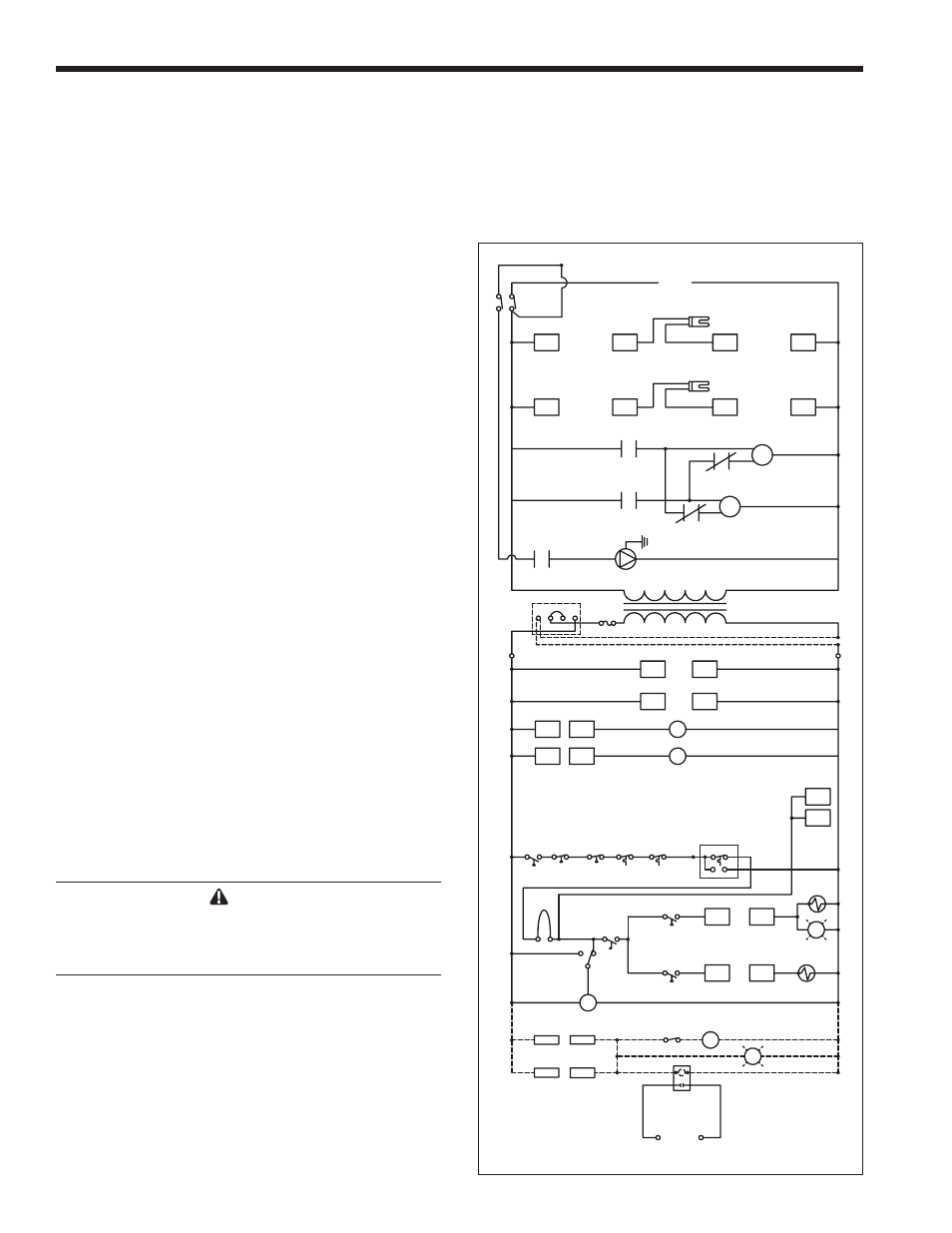
Figure 9. Wiring Schematic, sizes 1250-2000.
location is farther from the heater than the capillary
will reach to, then the control should be moved to the
remote location and the wires extended to the new
location of the control. If the controller needs to be
moved, and it is being moved to an outdoor location,
the control will need to be put in a weather-tight
enclosure to protect it from rain, snow, etc.