LAARS Mighty Therm2 MT2P (Sizes 500–2000 MBTU/h) - Install and Operating Manual User Manual
Page 10
LAARS Heating Systems
Page 10
to accommodate horizontal vent sizes, shown in
Table 1.
WARNING
The outdoor vent terminal gets hot. Unit must be
installed in such a way as to reduce the risk of burns
from contact with the vent terminal.
2.3.2 Side Wall Combustion Air Terminal
Never obtain combustion air from the pool area.
Corrosion of and/or damage to the pool heater may
result. The Laars side wall combustion air terminal
(
listed in Table 1
) must be used when the unit takes
its combustion air through a duct from a side wall.
Consider the following when installing the terminal:
1. Do not locate the air inlet terminal near a source
of corrosive chemical fumes (e.g., cleaning fluid,
chlorinated compounds, etc.)
2. Locate the terminal so that it will not be subject to
damage by accident or vandalism.
3. Locate the combustion air terminal so that it
cannot be blocked by snow. The National Fuel
Gas Code requires that it be at least 12 inches (30
cm) above grade, but the installer may determine
it should be higher, depending upon local
conditions.
4. If the MT2P is side-wall vented to the same wall,
locate the vent terminal at least 3 feet (0.9m)
horizontally from the combustion air terminal,
and locate the vent terminal at least 1 foot (0.3m)
above the combustion air terminal (see Figure 3).
2.3.3 Vertical Vent Terminal
When the unit is vented through the roof, the
vent must extend at least 3 feet (0.9m) above the point
at which it penetrates the roof. It must extend at least
2 feet (0.6m) higher than any portion of a building
within a horizontal distance of 10 feet (3.0m), and high
enough above the roof line to prevent blockage from
snow. When the combustion air is taken from the roof,
the combustion air must terminate at least 12" (30cm)
below the vent terminal (
see Figure 2
).
2.3.4 Vertical Combustion Air Terminal
When combustion air is taken from the roof, a
field-supplied rain cap or an elbow arrangement must
be used to prevent entry of rain water (
see Figure 2
).
The opening on the end of the terminal must be at least
12" (30cm) above the point at which it penetrates the
roof, and high enough above the roof line to prevent
blockage from snow. When the vent terminates on the
roof, the combustion air must terminate at least 12"
(30cm) below the vent terminal.
2.4 Vent Terminals for Outdoor Units
For outdoor applications, the vent and combustion
air openings must be covered with proper terminals to
prevent rain, snow and other objects from falling into
the Mighty Therm2.
If local codes allow, outdoor installations may
use 1' of appropriately sized galvanized single wall or
BVent and a rain cap for exhaust vent termination in
the default configuration (venting out of the top). Note
that some local codes may require a higher vertical
vent height, extending above any perimeter fencing,
etc. In installations where the appearance of the vent is
objectionable, the low profile vent terminals in
Table 6
may be used.
Combustion air inlets consist of appropriately
sized galvanized pipe and elbows to allow the open
end to face down aside the boiler. This is available as a
DISTANCE FROM GAS METER
OR LAST STAGE REGULATOR
MODEL AND
GAS TyPe
0-100' 0-31m 100-200' 31-61m 200-300' 61-91m
500 natural
1-1/2" 3.8cm 2"
5.1cm 2"
5.1cm
500 propane 1" 2.5cm 1-1/2" 3.8cm 1-1/2" 3.8cm
750 natural 2" 5.1cm 2"
5.1cm 2-1/2" 6.4cm
750 propane 1-1/2" 3.8cm 1-1/2" 3.8cm 2"
5.1cm
1000 natural 2" 5.1cm 2-1/2" 6.4cm 3"
7.6cm
1000 propane 1-1/2" 3.8cm 2"
5.1cm 2-1/2" 6.4cm
1250 natural 2-1/2" 6.4cm 2-1/2" 6.4cm 3"
7.6cm
1250 propane 2"
5.1cm 2"
5.1cm 2-1/2" 6.4cm
1500 natural 2-1/2" 6.4cm 3"
7.6cm 3"
7.6cm
1500 propane 2"
5.1cm 2-1/2" 6.4cm 2-1/2" 6.4cm
1750 natural 2-1/2" 6.4cm 3"
7.6cm 3"
7.6cm
1750 propane 2"
5.1cm 2-1/2" 6.4cm 2-1/2" 6.4cm
2000 natural 3" 7.6cm 3"
7.6cm 3-1/2" 8.9cm
2000 propane 2-1/2" 6.4cm 2-1/2" 6.4cm 3"
7.6cm
Notes:
1. These figures are based on 1/2" (0.12kPa) water column
pressure drop.
2. Check supply pressure and local code requirements before
proceeding with work.
3. Pipe fittings must be considered when determining gas pipe
sizing
.
Table 7. Gas Piping Size.
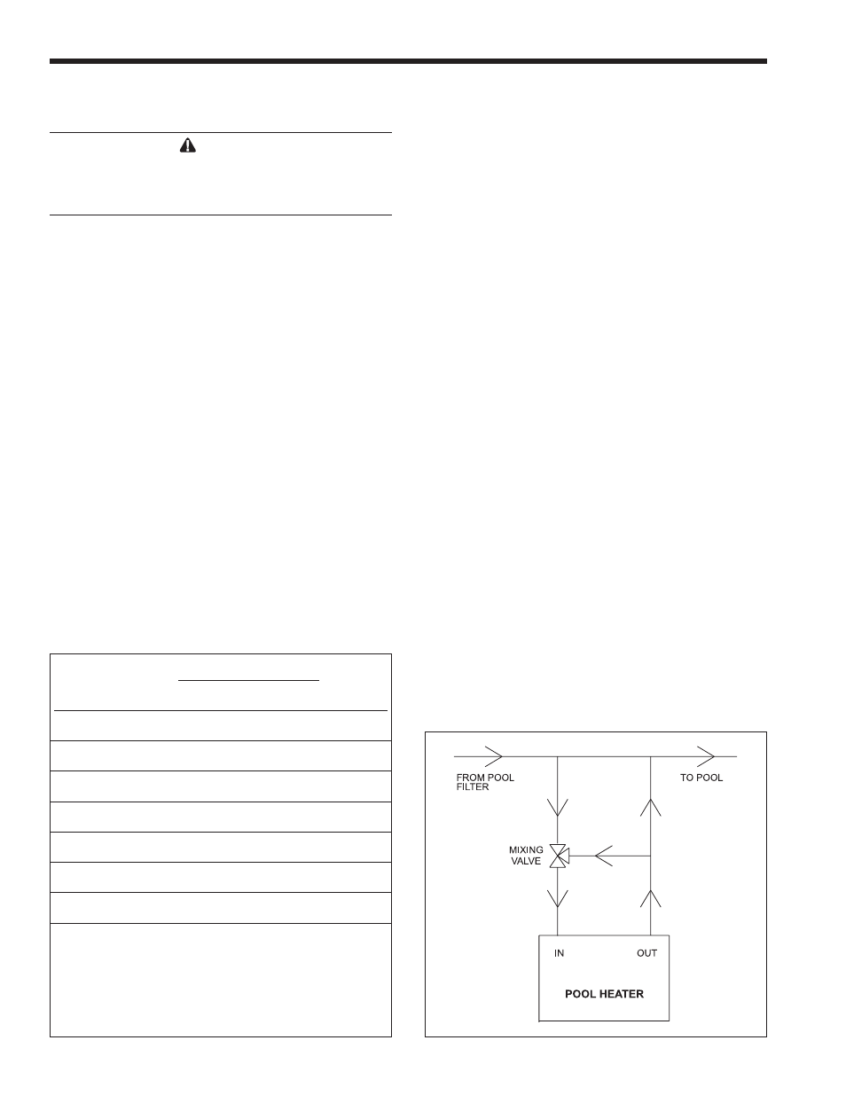
Figure 4. Mixing System.