2d. freeze protection, 2e. gas supply and piping – LAARS Mighty Therm HH (Sizes 2000-5000) - Installation, Operation and Maintenance Instructions User Manual
Page 8
LAARS Heating Systems
Page 8
wind conditions are possible, locate the boiler
at least three (3) feet from the structures.
3.
Never install the boiler under any kind of roof
overhang. Do not locate the boiler below or
adjacent to any doors, windows, louvers, grills,
etc. which communicate in any way with an
inhabited area of a building. Even though such
communication might be through another
structure such as a garage or utility room (see
Figure 6).
2D. Freeze Protection
Boiler installations are not recommended in
areas where the danger of freezing exists unless
proper precautions are made for freeze protection.
Maintaining a mixture of 50% water and 50%
ethylene glycol is the preferred method of freeze
protection for hydronic systems. This mixture will
protect the boiler to temperatures of about -35°F. To
get the desired temperature rise across the boiler
when this mixture is used, increase the G.P.M. flow
recommended for water by 15%. Increase the head
loss requirement by 20%.
2E. Gas Supply and Piping
Review the following instructions before
proceeding with the installation.
1.
Verify that the boiler is fitted for the proper
type of gas by checking the rating plate. Laars
boilers are normally equipped to operate below
a 2000 foot altitude. Boilers equipped to
operate at higher altitudes have appropriate
stickers or tags attached.
2.
Use the figures in Table 4 to provide adequate
gas piping (check local code for BTU capacity
required).
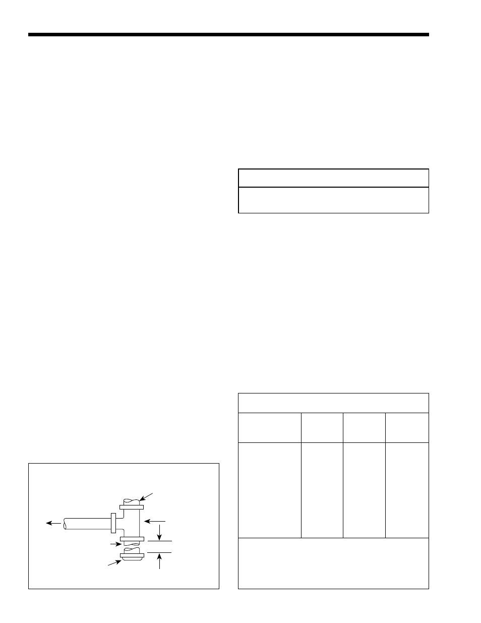
3.
A trap (drip leg) must be provided ahead of the
gas controls (see Figure 7). Where required by
code, provide a second manual gas shutoff
valve. Do not remove manual valve furnished
with the boiler.
4.
The boiler and its individual shutoff valve must
be disconnected from the gas supply piping
system during any pressure testing of that system
at test pressures in excess of ½ psig. The boiler
must be isolated from the gas supply piping
system by closing its individual manual gas
shutoff valve during any pressure testing of the
gas supply piping system at test pressures equal
to or less than ½ psig.
5.
Provide gas supply pressure to the boiler as
follows:
Natural Gas
LPG
Min. (inches water column) 7 11
Max.(inches water column) 9 14
Note: The boiler and all other gas appliances
sharing the boiler gas supply line must be firing at
maximum capacity to properly measure the inlet
supply pressure. Low gas pressure could be an
indication of an undersize gas meter and/or obstructed
gas supply line.
6.
The correct burner manifold gas pressure is
stamped on the rating plate. The regulator is pre-
set at the factory, and normally requires no
further adjustment.
7.
The gas manifold and control assembly was
tested and conform to the safe lighting and other
performance criteria specified in the latest
editions of ANSI Z21.13 and CGA 3.3 Low
Pressure Boiler Standard.
Gas Supply
Inlet
Tee
Fitting
3" Min.
Nipple
Cap
To
Equipment
Inlet
Distance from Gas Meter or Last Stage Regulator
Indoor
Outdoor
0-100'
100-200'
200-300'
Size
Size
Nat.
Pro.
Nat.
Pro.
Nat.
Pro.
2000
------
2½
2
3
2½
3
3
2450
2200
3
2½
3
2½
3½
3
3050
2800
3
2½
3½
3
3½
3
3500
3200
3
2½
3½
3
4
3½
4050
3600
3½
3
4
3½
4
3½
4500
4000
3½
3
4
3½
5
4
5000
4500
4
3½
4
3½
5
4
NOTES:
These figures are based on 1/2" water column pressure drop.
Check supply pressure and local code requirements before
proceeding with work.
Pipe fittings must be considered when determining gas pipe sizing.
Figure 7. Method of Installing a Tee Sediment Trap.