LAARS Mighty Therm HH (Sizes 2000-5000) - Installation, Operation and Maintenance Instructions User Manual
Page 4
LAARS Heating Systems
Page 4
1B. Flow Requirements
All low volume hydronic boilers must have
continuous flow through the heat exchanger when
firing, for proper operation. The system pump must be
capable of developing sufficient pressure to overcome
the resistance of the boiler plus the entire circulating
system at the designated GPM (see Table 1). The
temperature rise across the boiler should never exceed
40° F.
NOTE: Water entering boiler should be 105°F
minimum.
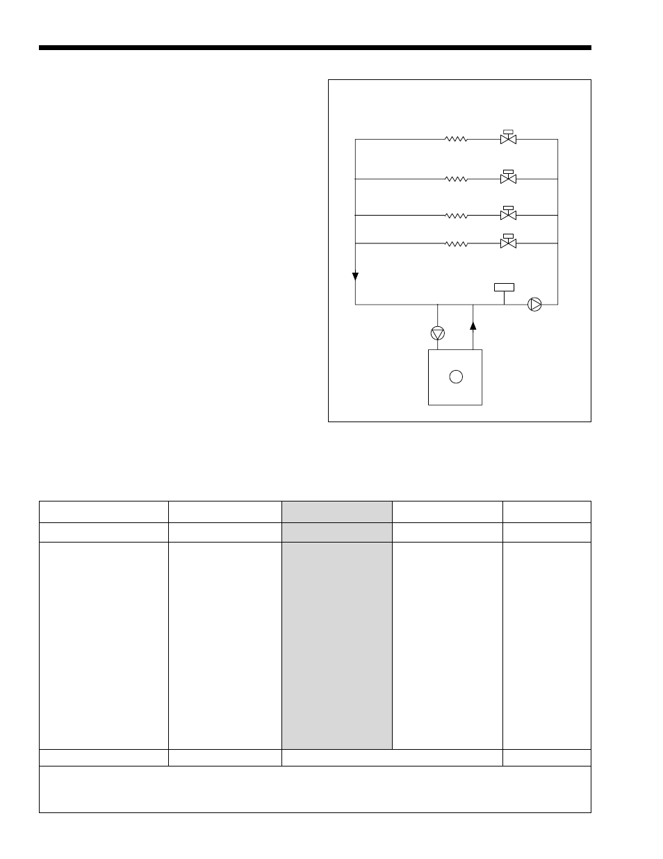
1C. Variable Water Flow Systems
Heating systems using zone valves, zone pumps
or 3-way valves can experience reduced water flow
through the boiler. This can result in an excessive
water temperature rise and unstable boiler operation. If
system water flow is variable, it must not be allowed
to fall below 30% of full flow. The boiler must be
equipped with staged or modulated fire with the
temperature sensor installed in the outlet water. State
variable flow when ordering. Laars recommends
primary-secondary pumping for all variable flow
systems. Primary-secondary pumping is mandatory for
variable flow systems where minimum flows are less
than 30% of full flow conditions. The boiler pump in a
primary-secondary system maintains constant flow
through the boiler even though the system flow is
variable. In a primary-secondary system the pressure
drop of the boiler is not added to the system (see
Figure 2).
Fan Coils
Zone Valves
Compression Tank
System Pump
Pump
(Location varies
with model)
Unit
12"
Max.
Convectors Baseboards
or Fan Coils
20°F
25°F
30°F
35°F
Size (I)
Size (E)
GPM
H/L
GPM
H/L
GPM
H/L
GPM
H/L
20001P
------
164
3.91
131
3.6
109
1.8
94
0.7
2P
------
164
10.5
131
7.4
109
4.9
94
3.0
24501P
22001P
201
5.9
161
3.9
134
3.8
115
2.3
2P
2P
201
16.4
161
10.2
134
7.7
115
5.7
30501P
28001P
250
9.3
200
5.9
167
4.5
143
3.8
2P
2P
*
*
200
16.4
167
12.5
143
8.5
35001P
32001P
284
12.0
230
8.7
189
5.7
164
3.9
2P
1P
*
*
*
*
189
16.8
164
10.5
40501P
36001P
332
17.2
266
11.9
222
8.1
190
5.8
2P
2P
*
*
*
*
222
24.0
190
16.0
45001P
40001P
369
21.75
295
13.2
246
10.0
211
7.0
2P
2P
*
*
*
*
*
*
211
20.0
50001P
45001P
410
27.0
328
16.8
273
13.0
234
9.0
2P
2P
*
*
*
*
*
*
*
*
HIGH
NORMAL
LOW
* Not recommended, consult factory.
I=Indoor, E=Outdoor. GPM=Water flow. H/H=Pressure drop (head loss)through the boiler, expressed in Ft. of H
2
0. 1P=Single-pass heat exchanger.
2P=Two-pass heat exchanger. Shaded area is the recommended flow and temperature rise.
Figure 2. Primary-Secondary System.
Table 1. Water Flow, Temperature Rise and Pressure Drop.