1d. warning regarding chilled water systems, 2a. boiler placement – LAARS Mighty Therm HH (Sizes 2000-5000) - Installation, Operation and Maintenance Instructions User Manual
Page 5
Mighty Therm Hydronic Boiler
Page 5
1C-1. A Special Note About 3-Way
Water Valves
3-way water valves (2 position or proportional)
are sometimes used to divert water around a boiler and
control the temperature of water being supplied to the
system. Valves installed in this manner must be
supplied with an end switch or some other suitable
control to shut off the boiler when the flow is reduced
to 30%. The boiler must be supplied with staged or
modulated fire as indicated in Section 1C, Variable
Water Flow Systems.
It is often possible to accomplish excellent water
temperature control without 3-way valves through
proper application of staged or modulated firing
systems. Consult the factory or local Laars
representative for assistance with such systems.
1C-2. System Pressure Requirements
The Model HH boilers are designed to operate
on closed, pressurized systems. A minimum of 12 psi
should be maintained on the system where boiler
supply water temperatures are 200°F or less. If higher
temperatures are required, the minimum system
pressure should be at least 15 psi above the water
vapor pressure corresponding to the elevated water
temperature.
The Model HH boilers are not suitable for
open systems unless the supply water temperatures are
kept below 180°F, and a minimum of 5 psi static head
is maintained at the boiler.
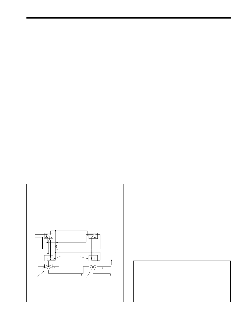
1D. Warning Regarding Chilled
Water Systems
When a boiler is connected to an air conditioning
system where the same water is used for heating and
cooling, chilled water must be prevented from entering
the boiler. When changing such a system from cooling
to heating, the chilled water should be allowed to
circulate through the building after the chiller has been
turned off long enough for the water to warm up to at
least 70°F before the water is allowed to flow into the
boiler. It is equally important to prevent hot water
from entering the chiller. The system shown in Figure
3 is suggested to make sure that the system water is
neither too hot nor too cold when a changeover from
heating to cooling, or vice versa, takes place. When a
boiler is connected to heating coils located in air
handling units (where they may be exposed to
refrigerated air circulation), the boiler piping system
shall be equipped with a flow control valve or other
automatic means to prevent gravity circulation of
chilled water through the boiler. Chilled water in the
boiler will create condensate on the boiler tubes which
will drip on the burners and may extinguish the pilot.
Boilers installed in violation of either of the
above requirements may void the warranty.
SECTION 2.
Installation
2A. Boiler Placement
The boiler must be placed to provide clearances
on all sides for maintenance and inspection. There
must also be minimum distances maintained from
combustible surfaces.
All boilers must be installed on a non-
combustible floor. Under no circumstances can boilers
be installed on carpeting.
The National Fuel Code allows a boiler to be
placed on a combustible surface when such an
installation complies with the local codes. This code
specifies the surface under the boiler be protected with
hollow masonry no less than 4" thick, covered with
sheet metal at least 20 Ga. in thickness. Such masonry
DPDT Manual or Automatic
Change-over Switch
DPDT - Set at Change-over
Temperature
Clock Timer
Auto-resetting
Set at 15 minute SPDT
To Boiler
and
Chiller
From
System
To
System
3-Way Valve No. 2
To By-pass
Both Heater and
Chiller
3-Way Valve No. 1
Change-over
(Heating and Cooling)
From
Chiller
From
Boiler
Valve Motors
2-Pos
3-Wire - 24V
115/24V
Transformer
By-pass
Clearance
Indoor
Outdoor
From
(Inches)
(Inches)
Top
24
—
Water Connection Side
24
24
Opposite Side
24
24
Front
48
48
Rear
24
24
Vent
6
—
Suggested Wiring Diagram For
Tempering System Water at
Changeover from Heating to Cooling
Figure 3. Boiler-Chiller Installation.
Table 2. Minimum Clearances from Combusible Surfaces.