LAARS Mighty Therm HH (Sizes 2000-5000) - Installation, Operation and Maintenance Instructions User Manual
Page 15
Mighty Therm Hydronic Boiler
Page 15
7.
Water dripping in firebox.
Possible Cause What To Do
A. If boiler is used with an air
A.Install flow-check valve or
conditioning system, chilled
programmed bypass valve in
water may be flowing either
the system for change-over
by gravity or pressure
from heating to cooling.
through boiler and
creating condensation on
boiler tubes.
B. Tube in heat exchanger has
B.A tube failure always caused
overheated and ruptured.
by
(a) scale formation in the tube
or
(b) inadequate water flow
through the boiler.
SECTION 6.
Conversion of Series HH Boilers
from Indoor to Outdoor Model
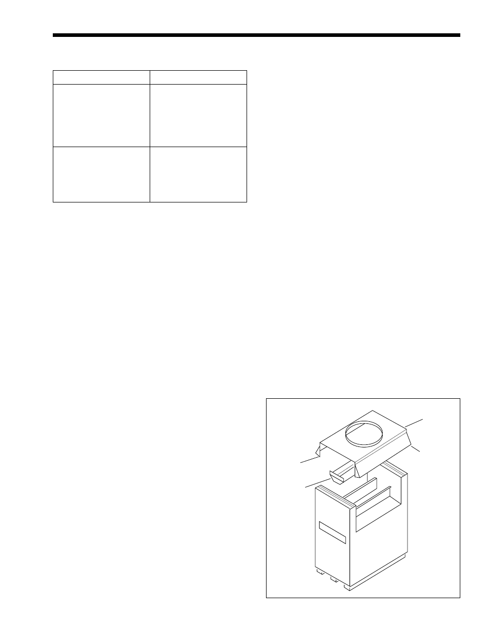
Please read the following instructions with
Figure 12.
Figure 13 shows the conversion completed.
Please follow the instructions in their numerical
order, failure to do this will cause problems on
assembly.
1.
Remove top panel, (1) (see Figure 12).
2.
Remove front and rear upper panels, (2)
(see Figure 12).
3.
Remove front and rear wings LH & RH, (3)
(see Figure 12).
4.
Remove diverter assembly, (4) (see Figure 12).
5.
Remove outer screw from upper end panel at
junction with lower end panel.
Outdoor Kit Parts List (see Figure 13)
Key No.
Part No.
5 ............................................................................. 20017100
6 ............................................................................. 20016900
7 ............................................................................. 20015101
............................................................................... 20015102
8 ............................................................................. 20016700
9 ............................................................................. 20017200
10 ........................................................................... 20017300
11 ........................................................................... 20017700
12 ........................................................................... 20016500
13 ........................................................................... 20016600
14 ........................................................................... 20016300
15 ........................................................................... 20014301
............................................................................... 20014302
16 ........................................................................... 20015200
17A Left Front Baffle (Single Inlet Manifold) ......... 20022200
17B Right Front Baffle (Single Inlet Manifold) ....... 20022300
17C Left Front Baffle (Split Inlet Manifold) ............ 20022000
17D Right Front Baffle (Split Inlet Manifold) ......... 20022100
18 ........................................................................... 20014601
............................................................................... 20014602
19 ........................................................................... 20016100
20 ........................................................................... 20018000
21 ........................................................................... 20016200
22 ........................................................................... 20017200
23 ........................................................................... 20017600
24 ........................................................................... 20018200
25 ........................................................................... 20018300
26 ........................................................................... 20018600
27 ........................................................................... 20015001
............................................................................... 20015002
28 ........................................................................... 20016800
1
2
3
4
Figure 12. Removal of Indoor Parts.