LAARS Mighty Therm HH (Sizes 2000-5000) - Installation, Operation and Maintenance Instructions User Manual
Page 10
LAARS Heating Systems
Page 10
2H. Filling Fully-Connected System
1.
Close all bleeding devices and open make-up
water valve. Allow system to fill slowly.
2.
If make-up water pump is employed, adjust
pressure switch on pumping system to provide a
minimum of 12 psi at the highest point in the
heating loop.
3.
If a water pressure regulator is provided on the
make-up water line, adjust the pressure regulator
to provide at least 12 psi at the highest point in
the heating loop.
4.
Open bleeding devices on all radiation units at
the high points in the piping throughout the
system, unless automatic air bleeders are
provided at such points.
5.
Run system circulating pump for a minimum of
30 minutes with the boiler shut off.
6.
Open all strainers in the circulating system and
check for debris.
7.
Recheck all air bleeders as described in Step 4.
8.
Check liquid level in expansion tank. With the
system full of water and under normal operating
pressure, the level of water in the expansion tank
should not exceed ¼ of the total, with the
balance filled with air.
9.
Start up boiler according to procedure described
in Section 3A. Operate the entire system,
including the pump, boiler, and radiation units
for one (1) hour.
10.
Recheck the water level in the expansion tank. If
the water level exceeds ¼ of the volume of the
expansion tank, open the tank drainer and drain
to that level.
11.
Shut down the entire system and vent all
radiation units and high points in the system
piping as described in Step 4.
12.
Close make-up water valve and check strainer in
pressure reducing valve for sediment or debris
from the make-up water line. Reopen make-up
water valve.
13.
Check gauge for correct water pressure and also
check water level in the system. If the height
indicated above the boiler insures that water is at
the highest point in the circulating loop, then the
system is ready for operation.
14.
Within three (3) days of start-up, recheck all air
bleeders and expansion tank as described in
Steps 4 and 8.
SECTION 3.
Operation
3A. Initial Start Up
Lighting: Safe lighting and other performance
criteria were met with the gas manifold and control
assembly provided on the boiler when it underwent
tests specified in the ANSI Z21.13 standard.
Before placing the boiler in operation, the
automatic safety shutoff devices must be checked.
Once the boiler is connected to the gas piping and
after all of the requirements in Section 2 have been
met, follow this procedure:
1.
Before beginning the tests, make sure the main
manual gas valve, and any other boiler firing
valves, are in the OFF position.
2.
Make sure the power switch on the boiler is in
the “ON” position. After placing the manual
pilot valves in the open position, and resetting all
safety devices (high limit, pressure switch, low
water cutoff, etc.), pilots can be lit following the
procedure located on the boiler rating plate.
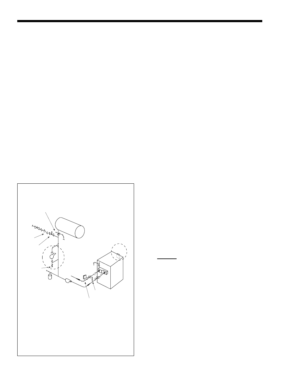
Air Changer
and Tank
Drainer
Make-up
Water
Supply
Check
Valve
Pressure
Reducing
Valve
Blow Down
Valve
Strainer
Pump
Temperature
and Pressure
Gauge
Thermometer
Method 2
To
Drain
To System
Method 1
To Drain
Compression
Tank
Notes: Select Method 1 or 2 when using Low Water Cutoff
accessory:
1. Under Method 1, the Low Water Cutoff is furnished by Laars and
shipped as a separate item for field installation.
2. Under Method 2, Electronic Low Water Cutoff is installed, wired
and tested on boiler in Laars factory.
3. Preferred location of system pump is shown. Compression tank
must always be on suction side of pump.
Figure 9. Boiler Piping.