2c. site location – LAARS Mighty Therm HH-PH (Sizes 175-400) - Installation, Operation and Maintenance Instructions User Manual
Page 5
Mighty Therm HH-PH Hydronic Boilers
Page 5
Heater
Heater
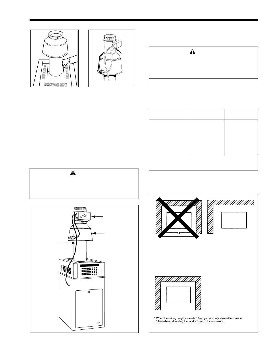
Closet Installation
(unacceptable)
Room Installation
(acceptable)
Alcove Installation
(acceptable)
A closet is any 4 sided enclosure
which is less than 16* times the
total volume of all the gas fired
appliances within the enclosure.
A room is any enclosure which is
at least 16* times greater than the
total volume of all the gas fired
appliances within the enclosure.
An alcove suitable for the
installation of a heater is a
restricted section of a room not
separated from the room by a door
or partition and which meets the
minimum clearances specified in
this manual.
* When the cieling height exceeds 8 feet, you are only allowed to consider 8
feet when calculating the total volume of the enclosure.
Figure 8. Vent Damper Installation (Models 175 and
250 only).
Figure 6. Drafthood with
Adapter Plate.
Figure 7. Drafthood Switch
Receptacle.
h.
Plug the wiring for the drafthood switch into the
receptacle on the left side of the vent damper box
(see Figure 7).
i.
Do not modify the automatic vent damper
device. The venting system must be arranged so
that only the boiler is served by the vent damper
device supplied with the boiler. Provide at least
six inches clearance between the automatic vent
damper and combustible construction, and be
sure to allow access for servicing the damper.
WARNING
Do not force motor operation when the operator is
fastened to the damper by moving the damper
blade, turning the shaft, or turning the position
indicator.
2C. Site Location
2C-1. Installation Information
WARNING
Improper installation or maintenance can cause
nausea or asphyxiation from carbon monoxide in
flue gases which could result in severe injury,
property damage, or death.
Locate the boiler to provide clearances on all
sides for maintenance and inspection. There must also
be minimum distances maintained from combustible
surfaces (see Table 1 and Figure 9).
Indoors
Outdoors
Clearance from:
inch mm
inch mm
Top
37
940
Unobstructed
Water conn. side
12
305
Unobstructed
Opposite side
6
152
6
152
Front
Alcove
Unobstructed
Rear
6
152
6
152
Vent*
6
152
—
Flooring
Combustible
Combustible
Service clearance = 36 inches (914mm) at front of heater,
and 18 inches (457mm) at water connection side.
*1" (25mm) if double wall vent is used.
Table 1. Minimum Boiler Clearances
From Combustible Surfaces.
VENT DAMPER
DRAFT HOOD
VENT DAMPER
HARNESS
Figure 9. Alcove Installation.