LAARS Mascot LX MLXC 175 MBH - Install and Operating Manual User Manual
Page 25
Mascot LX Boilers and Water Heaters
Page 21
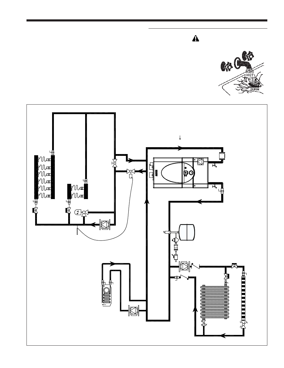
Figure 14. Hydronic Piping — High and low temp zones.
6.8 Piping Schematics
Figure 14 through Figure 19 illustrate typical piping
configurations for Mascot LX boilers. These diagrams
are only meant as a guide. All components or piping
required by local code must be installed.
CAUTION
Scalding Risk: Laars recommends
the use of a thermostatic mixing
valve at domestic hot water
outlet (boiler location) to
reduce potential for scalding.
Contact Laars for
recommended models.
_____________________________________________
Heat
in
g
S
up
pl
y
A
ir E
lim
in
at
or
S
ed
im
ent
tra
p
E
xpans
ion tank
and auto
fe
ed
Heat
in
g
Ret
ur
n
* *
* *
* *
*
C
los
el
y s
pac
ed t
ee'
s -
4
pi
pe d
iam
et
er
s apar
t
M
as
cot
L
X
- r
es
ide
nt
ia
l hi
gh
a
nd
low
te
mp.
zon
es
This manual is related to the following products:
- Mascot LX MLXC 150 MBH - Install and Operating Manual Mascot LX MLXC 125 MBH - Install and Operating Manual Mascot LX MLXH 220 MBH - Install and Operating Manual Mascot LX MLXH 175 MBH - Install and Operating Manual Mascot LX MLXH 150 MBH - Install and Operating Manual Mascot LX MLXH 125 MBH - Install and Operating Manual Mascot LX MLXH 100 MBH - Install and Operating Manual Mascot LX MLXH 75 MBH - Install and Operating Manual Mascot LX MLXH 50 MBH - Install and Operating Manual