2 check and adjustment of the corner load, Check and adjustment of the corner load – KERN & SOHN BAN 3T-3M User Manual
Page 14
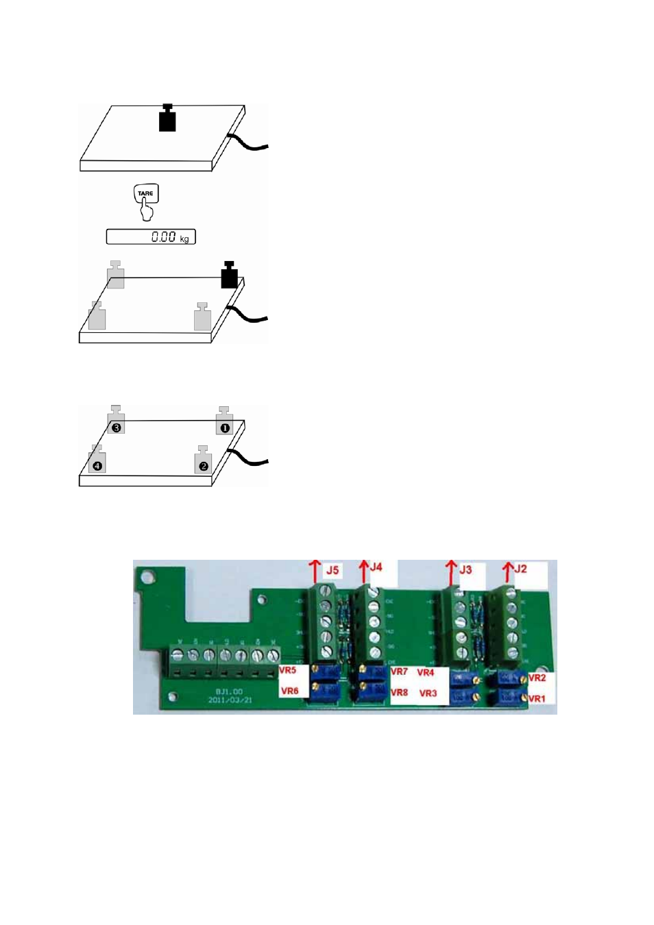
9.2 Check and adjustment of the corner load
Check of the corner load:
• Place the test weights in the centre of the load plate
and tare.
• The balance displays -0-.
• Place the test weights successively on all four
corners.
• Now the deviations are displayed with sign, write
down the values. If there are deviations out of the
tolerances (see chap. 9.1), an adjustment will be
necessary.
Adjustment of corner load:
Preparation:
• For a better control of the modifications which occur
during adjustment, select in the configuration menu
the highest readability for control purposes.
• Open connection box
Adjustment rule:
The corner (weighing cell) with the biggest negative
deviation must be set to zero. Do not re-adjust this
corner even after several adjustment sequences.
Adjustment on the analogue print
Adjustment of weighing cell J2 takes place at the pair of potentiometers VR2 and VR1.
Adjustment of weighing cell J3 takes place at the pair of potentiometers VR4 and VR3.
Adjustment of weighing cell J4 takes place at the pair of potentiometers VR8 and VR7.
Adjustment of weighing cell J4 takes place at the pair of potentiometers VR6 and VR5.
Increase the value turning to the right, reduce the value turning to the left.
Both potentiometers must be adjusted by the same number of turns.
KFP V40-IA-e-1110
14