Cisco 10008 User Manual
Page 28
28
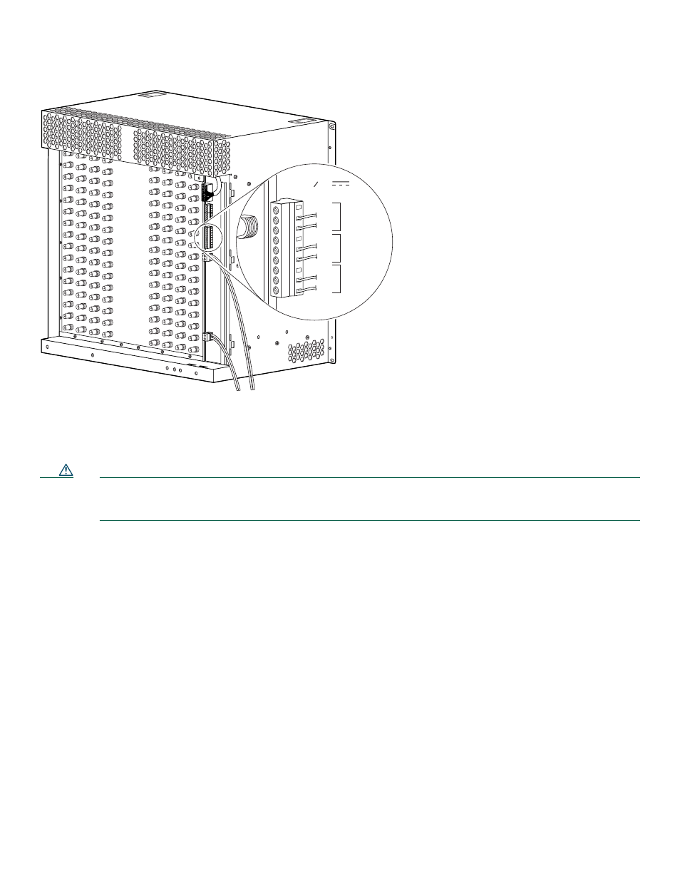
Figure 21
Alarm Indicator Terminal Block Connections
Step 4
Connect one set of alarm indicator wires to the alarm terminal block as follows:
a.
Connect one lead to the common (COM) terminal.
b.
Connect the other lead to the normally closed (NC) or normally open (NO) terminal.
Caution
shows the wiring configuration for normally open (NO) alarm relays. If you are wiring the router in series
with other equipment for the alarm indicators, use the normally closed (NC) terminals. If you are wiring the router
in parallel with other equipment for the alarm indicators, use the NO terminals.
Step 5
Repeat Step 3 and Step 4 for any remaining alarm indicators.
32694
MINOR
MAJOR
CRITICAL
ALARMS
50VA
SELV max
NC
COM
NO
NC
COM
NO
NC
COM
NO
See also other documents in the category Cisco Hardware:
- ASA 5505 (1994 pages)
- OL-15491-01 (268 pages)
- WUSB600N (43 pages)
- 10000 (556 pages)
- 10000 (12 pages)
- 3825 (358 pages)
- WRV54G (101 pages)
- WUSB54GC (33 pages)
- 2600 Series (10 pages)
- DPQ2202 (38 pages)
- 1600 (13 pages)
- WRT320N (53 pages)
- 1701 (10 pages)
- 300 (16 pages)
- 3200 Series (60 pages)
- 2900 SERIES XL (138 pages)
- 4430 (12 pages)
- 1005 (6 pages)
- 3500 Series (8 pages)
- GigaStack WS-X3500-XL (58 pages)
- WIRELESS-G WRT54GP2 (112 pages)
- 1604 (22 pages)
- 3600 Series (18 pages)
- WIRELESS LAN CONTROLLER OL-17037-01 (80 pages)
- DPC3000 (36 pages)
- 3545 MCU (56 pages)
- WRT110 (48 pages)
- 7300-6T3 (54 pages)
- 10BASE-FL (40 pages)
- 340 (62 pages)
- 1700 (14 pages)
- 1700 (88 pages)
- 12000 (60 pages)
- 3600 (18 pages)
- 1800 Series (12 pages)
- 2000 (6 pages)
- ACE XML OL-13877-01 (12 pages)
- 10720 (26 pages)
- 10008 (38 pages)
- 1-PORT G.SHDSL 2600 (22 pages)
- XM Universal Gateways Cisco AS5400XM (100 pages)
- 1710 (12 pages)
- WRTP54G (114 pages)
- 7201 (4 pages)