Link tx r x fa il, Carrier alarm loop fa il, Carrier alarm loop f ail – Cisco 10008 User Manual
Page 15: Fa il, Carrier alarm loop f a il, Carrier tx rx f ail
15
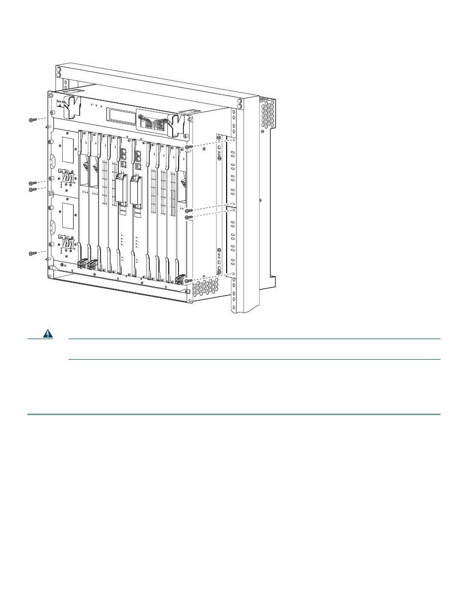
Figure 7
Attaching the Chassis to a 23-Inch 2-Post Rack
Warning
At least three people are required to mount the chassis in the equipment rack: two people are needed to hold the
chassis in place while a third person tightens the mounting screws. Statement 234
Step 3
Lift the chassis into position between the rack posts.
Step 4
Align the mounting bracket holes with the rack post holes.
Step 5
Insert the eight mounting screws through the mounting bracket into the rack, and tighten the screws. The third person
attaches the chassis to the rack.
Go to the
“Attaching the Cable-Management Bracket” section on page 16
to continue the installation process.
30015
1
3
2
4
0A
PROCESSOR ONL
Y
0B
5
6
7
8
PROCESSOR ONL
Y
POWER
FAULT
MISWIRE
POWER
FAULT
MISWIRE
CISCO
10000
LINK
TX
R
X
FA
IL
GIGABIT ETHERNET
CISCO
10000
C
A
R
R
IE
R
A
L
A
R
M
L
O
O
P
F
A
IL
CH OC-12-DSO SM-IR
CISCO
10000
CARRIER
ALARM
LOOP
FA
IL
6XCT3–DS0
0
5
4
3
2
1
CISCO
10000
CARRIER
ALARM
LOOP
F
AIL
6XCT3–DS0
0
5
4
3
2
1
FA
IL
PERFORMANCE R
O
UTING ENGINE
CONSOLE
S
TA
T
U
S
A
C
O
C
R
IT
IC
A
L
M
IN
O
R
M
A
JO
R
ETHERNET
LINK
A
CTIVITY
AU
X
S
LO
T 0
S
L
O
T
1
FA
IL
PERFORMANCE R
O
UTING ENGINE
CONSOLE
S
TA
T
U
S
A
C
O
C
R
IT
IC
A
L
M
IN
O
R
M
A
JO
R
ETHERNET
LINK
A
CTIVITY
AU
X
S
L
O
T
0
S
LO
T
1
CISCO
10000
CARRIER
ALARM
LOOP
FA
IL
6XCT3–DS0
0
5
4
3
2
1
CISCO
10000
CARRIER
ALARM
LOOP
FA
IL
6XCT3–DS0
0
5
4
3
2
1
CISCO
10000
CARRIER
ALARM
LOOP
F
A
IL
6XCT3–DS0
0
5
4
3
2
1
CISCO
10000
CARRIER
TX
RX
F
AIL
OC–12/STM–4 POS SM–IR
CISCO
10000
CISCO
10000
FANS
OK
FAN
FAILURE
MULTI-
FAN
FAILURE
When hot s
wapping this f
an tray,
removal and replacement m
ust
be done in under tw
o minutes or
system shutdo
wn will occur
.
CAUTION