Carrier MINIMUM LOAD CONTROL ACCESSORY 30XA080-500 User Manual
Page 8
Manufacturer reserves the right to discontinue, or change at any time, specifications or designs without notice and without incurring obligations.
Catalog No. 04-53300010-01
Printed in U.S.A.
Form 30XA-6SI
Pg 8
12-06
Replaces: New
Book 2
Tab
5c
Copyright 2006 Carrier Corporation
Configure Unit for Minimum Load Control —
The controls must be configured for the minimum load control
operation. Use the Touch Pilot™ or the Navigator™ display to
configure the system. Refer to the 30XA Controls, Start-Up,
Operation, Service, and Troubleshooting manual for additional
information.
Complete the following steps to configure minimum load con-
trol with the Touch Pilot display:
1. Ensure the unit is in Local Off operating mode by looking
at the upper left hand corner of the group display. If the
unit is not in Local Off mode, press the Start/Stop button
to switch to the Local Off operating mode.
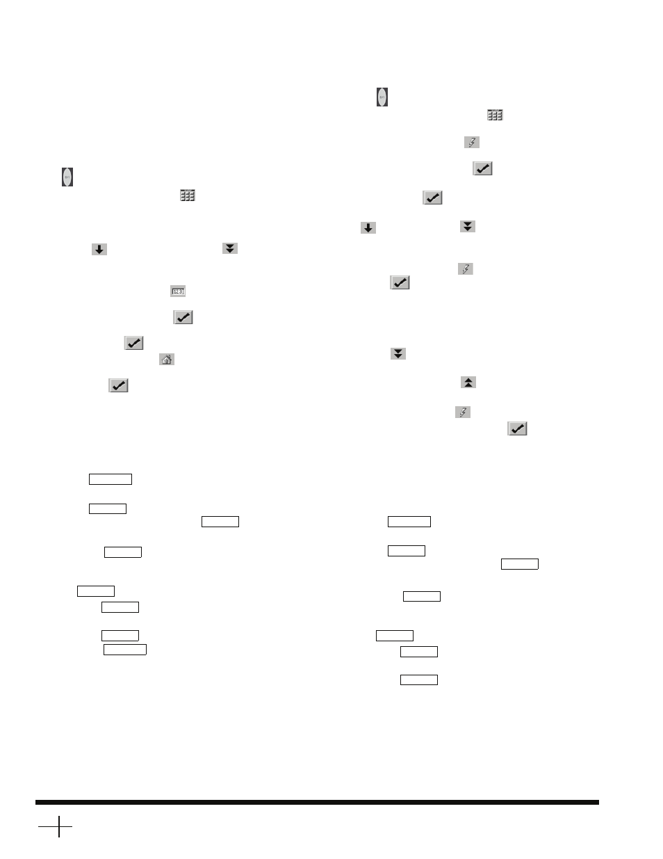
2. Press the main menu button
on the bottom line of the
display, and then select Service
→ Factory to navigate to
the factory table.
3. Scroll down the screen by pressing the Scroll Down
button
or the Page Down button
until Hot Gas
Bypass Select is displayed on the screen. Press Hot Gas
Bypass Select to display the Point Data dialog.
4. Press the Modify button
. If the login menu is dis-
played, log in with the password. The default password is
3333. Press the OK button
to confirm the input. The
value of hgbp_sel will display. Select Yes and press
the OK button
to confirm the input.
5. Press the Home button
on the bottom line of the dis-
play. A save confirmation menu will display. Press the
OK button
to confirm the action.
6. Wait 10 seconds and cycle the control power using the
Emergency On/Off switch (SW2).
The chiller is now configured for minimum load valve control.
Complete the following steps to configure minimum load con-
trol with the Navigator display:
1. Set the Enable/Off/Remote switch to the Off position.
2. Press
until the screen is blank and use the
arrow key to select the Configuration mode LED.
3. Press
, then use the arrow key to select the
sub-mode ‘UNIT’, then press the
key.
4. Press the down arrow key until ‘HGBP’ is displayed.
5. Press the
key. If the login menu is displayed,
log in with the password. The default password is 0 1 1 1.
Use the arrow keys to change each number’s value. Press
the
key after each number until finished.
6. Press the
key so that ‘No’ flashes.
7. Use the arrow keys to change the value to ‘Yes.’
8. Press the
key.
9. Press the
key until ‘DISP’ is displayed. Wait
10 seconds and cycle the control power using the Emer-
gency On/Off switch (SW2).
The chiller is now configured for minimum load valve control.
Test Minimum Load Relay Output —
Use the Touch
Pilot or Navigator display’s service test mode and the instruc-
tions given in their Controls, Start-Up, Operation, Service, and
Troubleshooting manuals to verify proper operation of the
solenoid(s).
For the Touch Pilot display:
1. Ensure the unit is in Local Off operating mode by looking
at the upper left hand corner of the group display. If the
unit is not in the Local Off mode, press the Start/Stop but-
ton to switch to the Local Off operating mode.
2. Press the Main Menu button
on the bottom line of
the display and then select Status
→ Quick Test Enable.
3. Press the Force button
. If the login menu is dis-
played, log in with the password. The default password is
3333. Press the OK button
to confirm the input.
4. The value of qck_test1 will display. Select On and press
the OK button
to confirm the input.
5. Scroll down the screen by pressing the scroll down button
or the page down
button until Cir. A Hot Gas
Bypass is displayed on the screen. Press Cir. A Hot Gas
Bypass Select to display the Point Data dialog.
6. Press the Force button
. Select On and press the OK
button
to confirm input.
7. Verify that the Cir. A minimum load valve (MLV) sole-
noid is energized.
8. Proceed to Cir. B Hot Gas Bypass and Cir. C Hot Gas By-
pass (30XA400-500 only) by pressing the page down
button
. Repeat Steps 5-7 for Cir. B MLV and Cir. C
MLV.
9. Use the page up button
to return to the top of the ta-
ble and select Quick Test Enable.
10. Press the Force button
.
11. Select Off and press the OK button
to disable Quick
Test.
12. Once the outputs have been tested, the installation is com-
plete. Return the Touch Pilot to Local Off operating
mode.
For the Navigator display:
1. Set the Enable/Off/Remote switch to the Off position.
2. Press
until the screen is blank and use the
arrow key to select the Service Test mode LED.
3. Press
, then use the arrow key to select the
sub-mode ‘QUIC’, then press the
key.
4. Press the down arrow key until ‘HGP.A’ is displayed.
5. Press the
key. If the login menu is displayed,
log in with the password. The default password is 0 1 1 1.
Use the arrow keys to change each number’s value. Press
the
key after each number until finished.
6. Press the
key so that ‘Off’ flashes.
7. Use the arrow keys to change the value to ‘On.’
8. Press the
key.
9. Verify that the Cir. A minimum load valve (MLV)
solenoid is energized.
10. Proceed to ‘HGP.B’ and ‘HGP.C’ (30XA400-500 only)
and repeat Steps 4-9 for Cir. B MLV and Cir. C. MLV.
11. Once the outputs have been tested, the installation is com-
plete. Return the Enable/Off/Remote contact switch to the
desired position.
ESCAPE
ENTER
ENTER
ENTER
ENTER
ENTER
ENTER
ESCAPE
ESCAPE
ENTER
ENTER
ENTER
ENTER
ENTER
ENTER