Carrier MINIMUM LOAD CONTROL ACCESSORY 30XA080-500 User Manual
Page 3
3
Table 2C — Contents of Accessory Kit, Part No. 00EFN900002900A
LEGEND
PART NUMBER
QUANTITY
DESCRIPTION
USAGE
00PSN500175200A
2
Tube assembly including solenoid valve,
ball valve, and 90 degree bend tube assembly
One per circuit (Circuit A and B for 30XA325, 350,
circuit A and C for 30XA450, 500). Cooler shell
minimum load port, connect to 30GX5034892 adapter.
30GX5034892
2
1 in. - 14 ORS x
1
/
2
in. NPT adapter
One per circuit. Cooler shell minimum load port.
00PPG000011600A
2
Solenoid coil assembly
One per circuit. Plug onto solenoid valve stub
on 00PSN500171700A tube assembly.
KA66AA062
4
5/8 in. tube clamp
Secure minimum load piping to the frame
as required.
DE40BA705
2
1
1
/
8
in. x 1
1
/
8
in. x
5
/
8
in. Tee
One per circuit. Discharge manifold on the side
of condenser coil V.
TH70400410
2
Cable assembly
One per circuit. Connect to solenoid coil
assembly and terminal block TB5 in control box.
00PPN500000401A
4
No. 10 screw
Mount tube clamps
32GB500432E
1
HGBP/Pump board
Mount in control box
TH70400864
1
Harness assembly
Wiring between TB5 and HGBP/Pump board
HH83ZB001
1
24V circuit breaker (CB14)
Mount on display bracket in control box
A6X10004352
4
No. 8 screw
Mount HGBP/Pump board
A6X10004434
4
Board mounting standoff
Mount HGBP/Pump board (325,350,450,500:
all voltages)
TH70400852
1
Communication cable assembly
30XA325,350,450,500: all voltages.
HY89TB010
3
Wire nut
Splice communication cable
HGBP — Hot Gas Bypass
ORS
— O-Ring Seal
TB
— Terminal Block
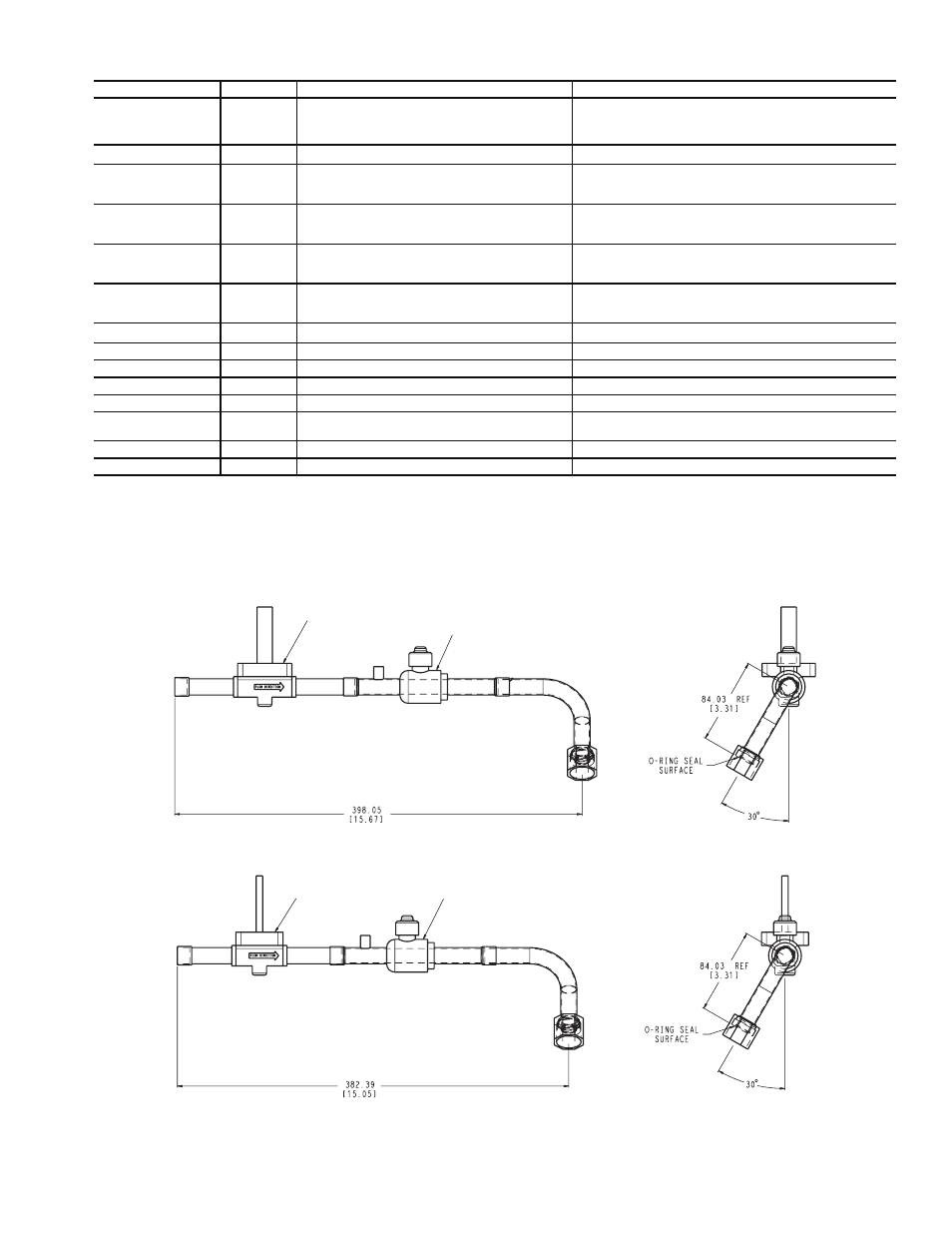
BALL VALVE
SOLENOID VALVE
TUBE ASSEMBLY 00PSN500175200A
SOLENOID VALVE
BALL VALVE
TUBE ASSEMBLY 00PSN500171700AA
NOTE: Dimensions are in mm [in.].
Fig. 1 — Dimensions of Tube Assemblies Provided in Accessory Kit
a30-4499
a30-4500