Intex CS15110 Krystal Clear 2012 User Manual
Page 11
163
SAVE THESE INSTRUCTIONS
Page 11
(163) MODEL CS15110 SAND FILTER PUMP & FILTER PUMP ENGLISH 7.5” X 10.3” PANTONE 295U 11/08/2011
English
PP
RR
OO
DD
UU
CC
TT
SS
PP
EE
CC
SS
&&
SS
EE
TT
UU
PP
II
NN
SS
TT
RR
UU
CC
TT
IIOO
NN
SS
PRODUCT SPECIFICATIONS
SETUP INSTRUCTIONS
Power:
110-120 Volt AC
Amperage:
Saltwater System - 0.9 A; Filter Pump - 3 A
Wattage:
Saltwater System - 100 W; Filter Pump - 370 W
Ideal Salt Level:
3000 ppm (parts per million)
Maximum Sanitizer Output/hour:
10 grams/hour
Copper Ionizer Output Current:
175mA
Maximum working pressure:
3.5 bar (50 psi)
Effective filtering area:
0.1 m
2
(1.1 ft
2
)
Maximum Flow Rate:
6050 liters/hour (1600 gallons/hour)
Recommended filtering media:
No. 20 silica sand or glass sand. Particle size
(Not included)
range 0.45 to 0.85 mm (0.018 to 0.033 inches).
Uniformity Coefficient less than 1.75.
Recommended filtering media quantity: No. 20 silica sand 25 Kg (55 Lbs) or glass sand
18 Kg (40 Lbs).
Limited Warranty:
see “Limited Warranty”
The sand filter removes suspended particles and sanitize your pool. Pool
chemistry is a specialized area and you should consult your local pool
service specialist for details.
TOOLS REQUIRED:
One (1) Phillips screwdriver
Pump location and mounting:
•
The system must be installed on a solid level and vibration-free base.
•
Provide a location protected from the weather, moisture, flooding and
freezing temperature.
•
Provide adequate access, space and lighting for routine maintenance.
•
Pump motor requires free circulation of air for cooling. Do not install
the pump in a damp or non-ventilated location.
A team of 2 or more people is recommended for setting up this product.
Motor pre-filtering assembly setup:
1.
Remove the sand filter and its accessories
from the packaging carefully and inspect for
any visible damage. If parts are damaged
contact your local service center listed at the
back of this owner’s manual.
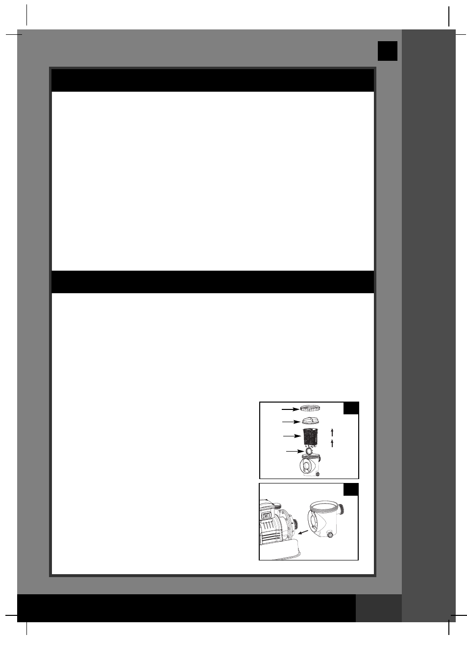
2.
In a counter-clockwise motion unscrew the leaf
trap cover (14) from the pre-filter housing. Take
out the basket (16) and filter housing nut (17)
(see drawing 10).
3.
Connect the pre-filter housing to the motor
water inlet. Note: Align the connector in the
pre-filter housing with the water inlet on the
motor (see drawing 11).
10
11
14
17
16
41