Carrier 50HCQA User Manual
Page 8
8
C06005
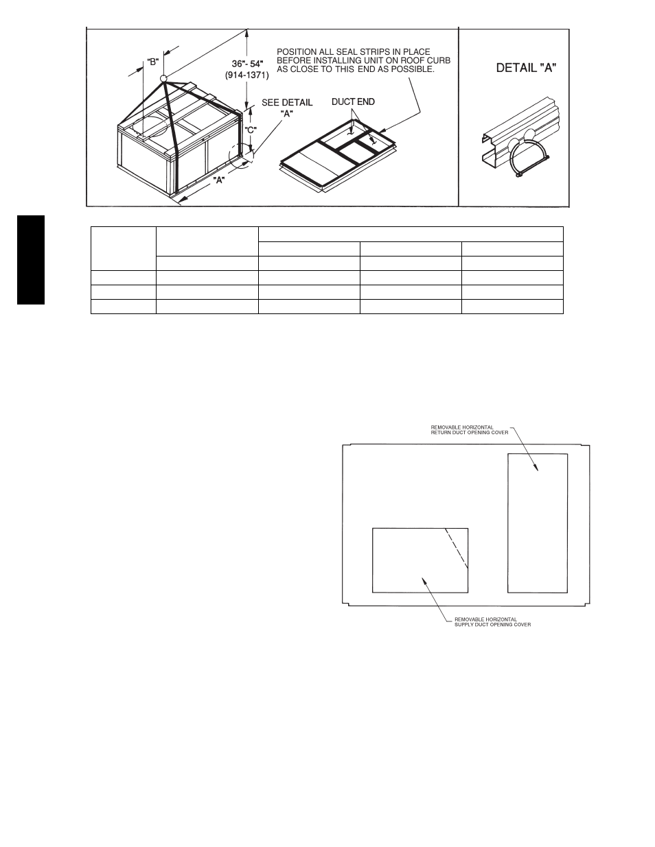
UNIT
MAX WEIGHT
DIMENSIONS
A
B
C
LB
KG
IN
MM
IN
MM
IN
MM
50HCQA04
725
330
74.5
1890
38.5
980
33.5
850
50HCQA05
845
384
74.5
1890
37.5
955
41.5
1055
50HCQA06
900
409
74.5
1890
37.5
955
41.5
1055
NOTES:
1. Dimensions in ( ) are in millimeters.
2. Hook rigging shackles through holes in base rail, as shown in detail “A.” Holes in base rails are centered around the
unit center of gravity. Use wooden top to prevent rigging straps from damaging unit.
Fig. 5 -- Rigging Details
Positioning on Curb —
Position unit on roof curb so that the following clearances
are maintained:
1
/
4
in. (6.4 mm) clearance between the
roof curb and the base rail inside the front and rear, 0.0 in.
clearance between the roof curb and the base rail inside on
the duct end of the unit. This will result in the distance
between the roof curb and the base rail inside on the
condenser end of the unit being approximately equal to
Fig. 3, section C--C.
Although unit is weatherproof, guard against water from
higher level runoff and overhangs.
After unit is in position, remove the compressor access
panel. Holding the blocking between compressors with
one hand, cut the strapping. Carefully remove the
blocking without damaging tubing, wiring, or controls.
Remove the strapping and replace the access panel.
Remove all shipping materials and top skid. Recycle or
dispose of all shipping materials.
Step 7 — Convert to Horizontal and Connect
Ductwork (when required)
Unit is shipped in the vertical duct configuration. Unit
without factory--installed economizer or return air smoke
detector option may be field--converted to horizontal
ducted
configuration.
To
convert
to
horizontal
configuration, remove screws from side duct opening
covers and remove covers. Using the same screws, install
covers on vertical duct openings with the insulation--side
down. Seals around duct openings must be tight. See
Fig. 6.
C06108
Fig. 6 -- Horizontal Conversion Panels
Field--supplied flanges should be attached to horizontal
duct openings and all ductwork should be secured to the
flanges. Insulate and weatherproof all external ductwork,
joints, and roof or building openings with counter flashing
and mastic in accordance with applicable codes.
Do not cover or obscure visibility to the unit’s informative
data plate when insulating horizontal ductwork.
50H
C
Q
A