CMC electronic MAI085MB User Manual
Page 32
mAI085-MB Actuator Interface Technical Manual /28
Distributive Intelligence
CMC INDUSTRIAL ELECTRONICS LTD
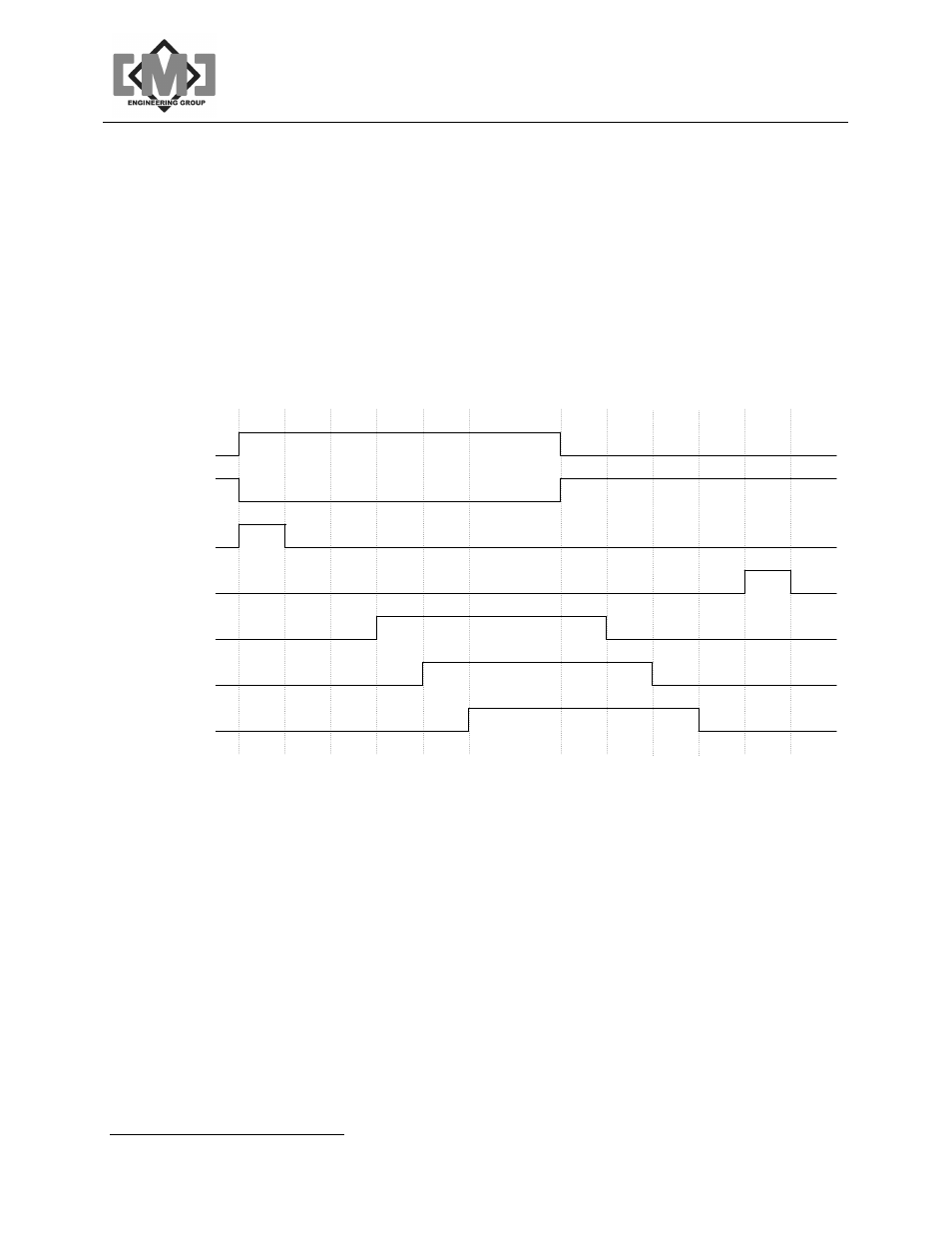
Figure 6 details a typical start/stop sequence for a conveying system.
E
n
te
rs
O
p
e
n
m
o
d
e
E
n
te
rs
C
lo
s
e
d
m
o
d
e
Output 1
Actuator 1
Close Lamp
Open lamp
Output 2
Actuator 2
Acutator 3
o
P
L
T
im
e
r
e
x
p
ir
e
s
o
D
L
T
im
e
r
e
x
p
ir
e
s
A
c
tu
a
to
r
1
o
D
L
T
im
e
r
e
x
p
ir
e
s
A
c
tu
a
to
r
2
o
D
L
T
im
e
r
e
x
p
ir
e
s
A
c
tu
a
to
r
3
o
D
L
T
im
e
r
e
x
p
ir
e
s
A
c
tu
a
to
r
1
c
D
L
T
im
e
r
e
x
p
ir
e
s
A
c
tu
a
to
r
2
c
D
L
T
im
e
r
e
x
p
ir
e
s
A
c
tu
a
to
r
3
c
D
L
T
im
e
r
e
x
p
ir
e
s
c
D
L
T
im
e
r
e
x
p
ir
e
s
c
P
L
T
im
e
r
e
x
p
ir
e
s
Figure 6 - Conveying System Timing Diagram