Before installation, Poe injector and splitter installation, 4 poe injector and splitter installation 4 – Interlogix POE302-SP User Manual
Page 10
4 IFS POE302-SP Ethernet Splitter User Manual
Before Installation
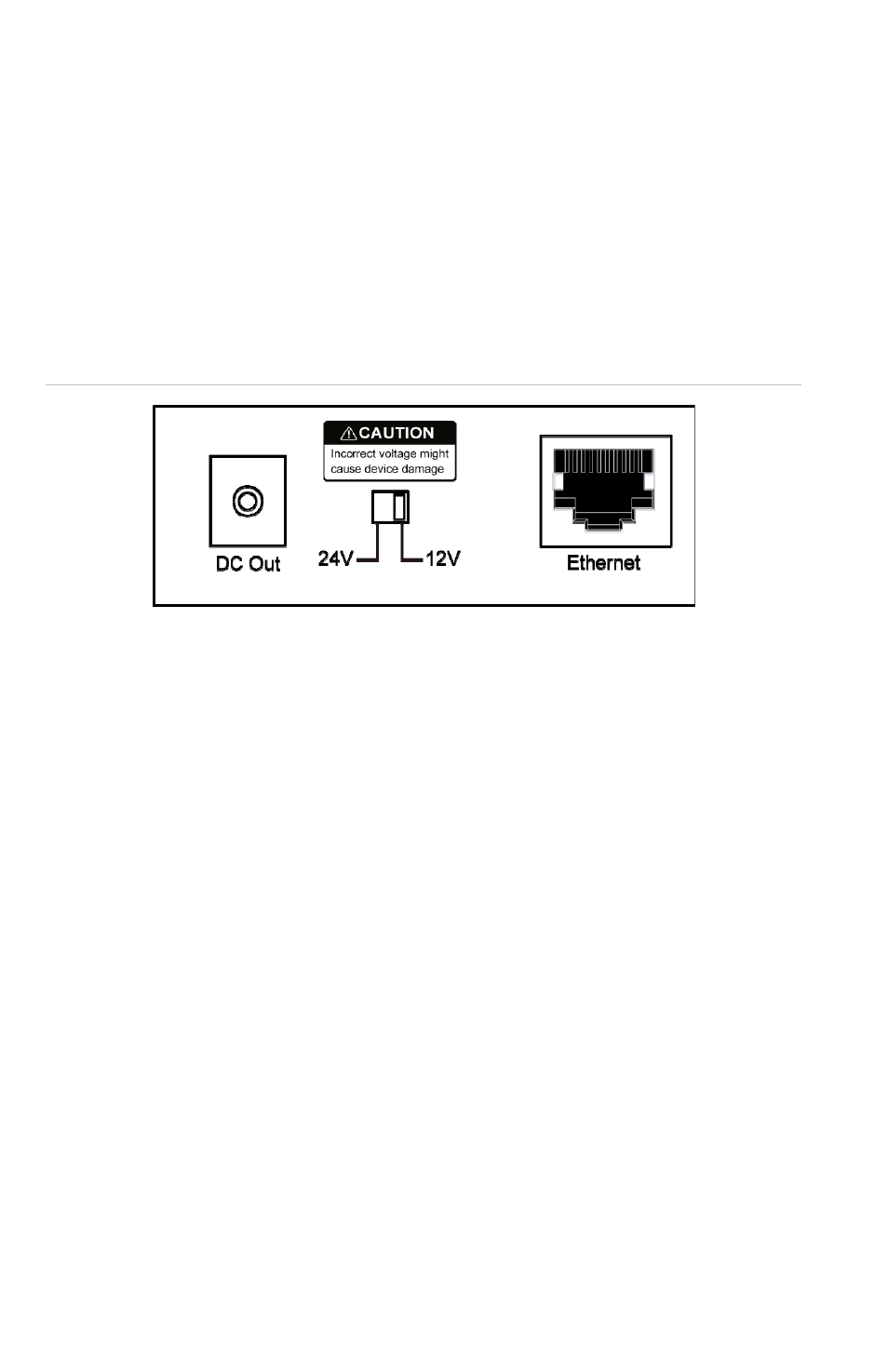
The POE302-SP separates data and power and provides two
DC power output options via a DIP switch.The two power
options are shown below.
• 12VDC/2A
• 24VDC/1A
Figure 2: Voltage output
The default switch setting is 12V.
Note:
Please check the power requirements of the device that
will be receiving its power from the POE302-SP. If the power
requirements (voltage and current) exceed the power output
that the POE302-SP can supply, a built-in current overload
circuit will shutdown the POE302-SP to protect it from
damage. Power will then not be supplied to the connected
device.
PoE Injector and Splitter Installation
The POE302-MS (PSE) and the POE302-SP (PD) can be
installed in pairs. However, use of third-party devices is
allowed only if the device complies with the IEEE 802.3at
Power over Ethernet standard.
1. Connect a standard network cable from "Ethernet+DC" port
of POE302-MS to "PoE In" port of POE302-SP. The POE
LED of POE302-SP / POE302-MS will be constantly on.