3 led indicators – Interlogix MC352-4P-2S User Manual
Page 11
- 11 -
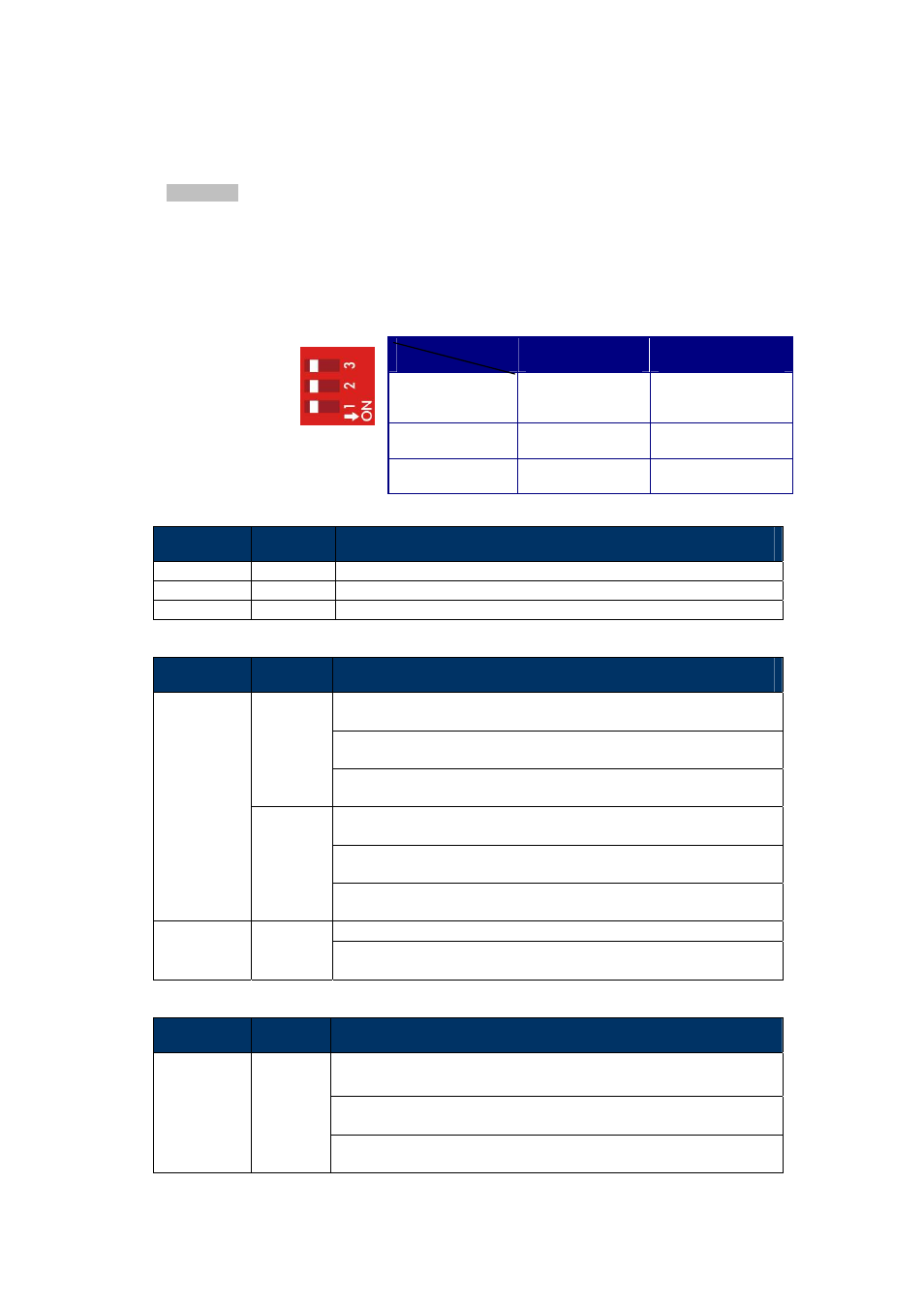
DIP Switch
The front panel of the MC352-4P-2Sprovides one 3-DIP Switch which is for configuring 100 or 1000X
fiber support and fiber redundant function.
Refer to the table below to know about the 3-DIP switch settings and descriptions:
For more information about the fiber redundancy function, please refer to the chapter 2.1.7 Redundancy
Overview.
2.1.3 LED Indicators
System
LED
Color
Function
P1
Green
Light
: indicates the power 1 has power.
P2
Green
Light
: indicates the power 2 has power.
FAULT
Green
Light
: indicates the either power 1 or power 2 has no power.
10/100/1000Base-T Interfaces
LED
Color
Function
Light
: indicates the Switch is successfully connecting to the network
at 1000Mbps.
Blink
: indicates that the Switch is actively sending or receiving data
over that port.
Green
OFF
: indicates that the Switch is inactively sending or receiving data
over that port.
Light
: indicates the Switch is successfully connecting to the network
at 10Mbps or 100Mbps.
Blink
: indicates that the Switch is actively sending or receiving data
over that port.
LNK/ACT
Orange
OFF
: indicates that the Switch is inactively sending or receiving data
over that port.
Light
: indicates the port is providing 52V DC in-line power.
PoE In-Use
(Port 1~4)
Orange
OFF:
indicates the connected device is not a PoE Powered Device
(PD).
100/1000Base-X SFP Interfaces (MC352-4P-2S)
LED
Color
Function
Light
: indicates the Switch is successfully connecting to the network at
100/1000Mbps.
Blink
: indicates that the Switch is actively sending or receiving data
over that port.
LNK/ACT
Green
OFF
: indicates that the Switch is inactively sending or receiving data
over that port.
OFF
ON
Fiber Redundant
(DIP 3)
Fiber Redundant
Switch
Port 6 (DIP 2)
1000X
100FX
Port 5 (DIP 1)
1000X
100FX