Wiring, Dip switch settings, Power up – Interlogix NX-548E User Manual
Page 3
4 Run a 3-conductor, 22 or 18 gauge (0.65 or 1.02 mm)
stranded wire cable from the module wire access hole
location to the panel (
5. Secure the back plate to the wall with the pan head
screws provided.
6. To assemble the antenna shrouds, attach the proper
number of sections together, then attach the top cap.
7. Install each antenna shroud on top of the back plate.
8. Remove the transceiver circuit board from the antistatic bag
Caution:
You must be free of static electricity before handling
circuit boards. Touch a bare metal surface or wear a grounding
strap to discharge yourself.
9. To install the circuit board onto the back plate (
),
insert the antennas into the antenna shrouds, then gently
slide the top of the circuit board under the two top latches,
and snap the circuit board in at the bottom latch to secure
it in place.
Figure 7. Circuit board and back plate
ON ECE
ON
ECE
1 2 3 4
1 2 3 4
Circuit board
Wiring terminals
LEDs
DIP switches
Top latches
Bottom latch
Antenna shrouds
Back plate
Wiring
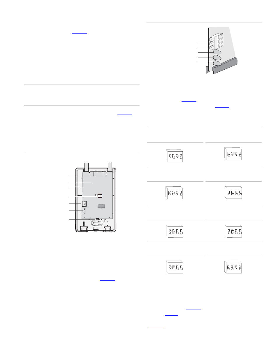
To wire the receiver, do the following:
1. Remove power (if applied) from the control panel. Use 22-
gauge, or larger, stranded wire to connect the +12, GND,
and DATA terminals on the receiver (
) to the
power, common, and data terminals on the control panel.
Figure 8. Receiver wiring connections and LEDs
+ 12 (to panel POS)
GND (to panel COM)
DATA (to panel DATA)
Green (power) LED
Red (data) LED
Red (not used) LED
DIP switch settings
The DIP switches (
) on the circuit board are used to
set the receiver module number. Use
switches to the desired module number.
Table 2. DIP switch settings
Module number 32
ON
1
2
4
3
EDG
Module number 33
ON
1
2
4
3
EDG
Module number 34
ON
1
2
4
3
EDG
Module number 35
ON
1 2
4
3
EDG
Module number 36
ON
1 2
4
3
EDG
Module number 37
ON
1 2
4
3
EDG
Module number 38
ON
1 2
4
3
EDG
Module number 39
ON
1
2
4
3
EDG
Power up
When you apply power to the control panel, the green (power)
LED on the receiver (
) blinks for approximately 10
describes the receiver status based on LED
conditions. The lower red LED at the bottom of the receiver
(
) may emit a dim glow, but is not used as an indicator
NetworX NX-548-E Receiver Installation Instructions
3