Intek RheoVac 950A User Manual
Page 40
-C3-
I:\OFFICE\WPMANUAL\RV950A Appendix C revB.doc
Feb. 4, 2010
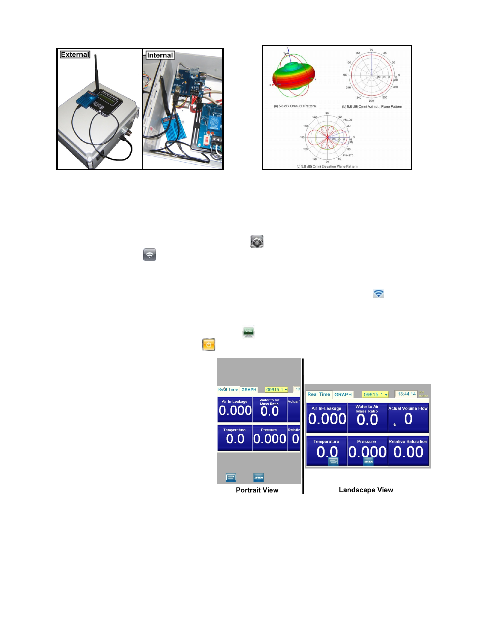
Figure C1.4: Wireless Antenna Connection
Figure C1.5: Typical Wireless Antenna Signal
Range
The following instructions assume the main electronics are on and connected to a RheoVac probe, the
HUI is on and unlocked, and that the wireless antenna is connected.
C.1.3.A HUI
Wi-Fi Settings
1. From the HUI home screen, choose settings
.
2. Select
Wi-Fi
.
3. Under ‘Choose a Network’, make sure the Rxxxxx_AP network is selected. (Note: xxxxx is
the serial number of the main electronics.)
4. After a short period of time, a Wi-Fi symbol will appear in the upper left corner
.
5. Return to the home screen.
C.1.3.B
Running the Connection Application
1. On the home screen, select the VNC icon
.
2. Click/touch the orange button
.
3. Select
‘RheoVac’ from the
connection list.
4. The screen will display
‘connecting’ and ‘VNC
Negotiating’.
5. The user interface seen in
Figure C1.6 will be visible
when the HUI is connected.
The user interface is designed to
be viewed while holding the
HUI horizontally in landscape
mode.
Figure C1.6: RheoVac Model 950 User Interface
C.1.4
USING THE USER INTERFACE
Basic Features – The display screen shows the following function fields: real time and graphing tabs,
probe under view, last update time, keyboard, and VNC menu.