Intek RheoVac 950A User Manual
Page 14
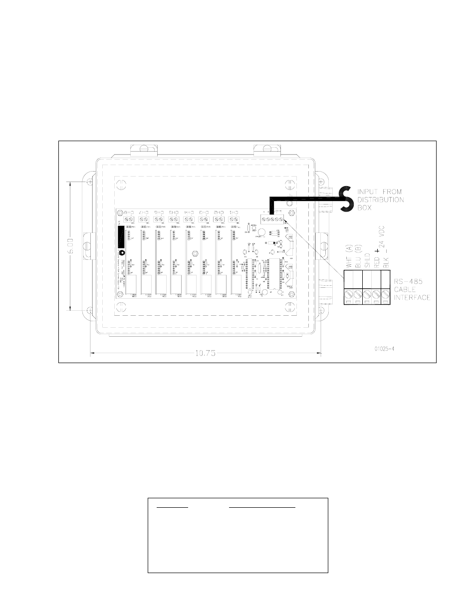
C. Transmitter Box (optional, see Figure 8) — For driving eight (8) remote 4-20 mA analog
signals from one RS-485 input port.
Note: Intek recommends using the network
connection for all data transmissions and RheoVac communications.
1. Connect the RS-485 communications/power cable from the distribution box (RS-485:
white and blue wires; 24Vdc power: red and black wires).
2. Connect up to eight (8) signal wire pairs to the indicated terminals for isolated 4-20mA
outputs.
Figure 8 Optional Transmitter Box
3. Figure 8 provides the RheoVac wiring detail for the 8 channel 4-20 mA outputs. Table
2 provides the appropriate connection identification. Model 950 transmitters are
configured as active (transmitter sources the current) when shipped. To change to the
passive mode (receiver to source the current), extract each small 4-20 board, find the
JP1 pins, and move the two jumpers from the “Act” pins to the “Pass” pins (two
positions to the right of factory settings). Figure 9 shows the current output circuit.
The figure also illustrates the active mode and the passive mode configurations.
Table 2 Optional 4-20 mA Configuration
Channel
Output Parameter
1
Actual Volume Flow
2
Total Mass Flow
3
Water Vapor Flow
4
Pressure
5
Water Vapor/Air Mass Ratio
6
Relative Saturation
7
Air In-Leak
8
Temperature
- 12 -