E.2.5 hall effect sensors – Haltech E6S User Manual
Page 119
119
JUMPER
JUMPER FUNCTION
ON
OFF
1
RELUCTOR HOME CHANNEL AMPLIFIER GAIN
4.3
1
2
RELUCTOR TRIGGER CHANNEL AMPLIFIER GAIN
4.3
1
3
RELUCTOR HOME CHANNEL PEAK DECAY
SLOW
FAST
4
RELUCTOR TRIGGER CHANNEL PEAK DECAY
SLOW
FAST
5
MULTITOOTH RELUCTOR VOLTAGE THRESHOLD (SEE NOTES)
LOW
6
SPARE ANALOG INPUT (SECOND TRIM) GAIN
0-5V
0-1V
7
EIGHT OR FOUR INJECTOR DRIVERS (SEE NOTES)
8
EIGHT OR FOUR INJECTOR DRIVERS (SEE NOTES)
9
RELUCTOR HOME CHANNEL % OF PEAK THRESHHOLD
50%
70%
10
RELUCTOR TRIGGER CHANNEL % OF PEAK THRESHHOLD
50%
70%
11
MULTITOOTH RELUCTOR VOLTAGE THRESHOLD (SEE NOTES)
MED
Notes:
If J5 and J11 are both on , the multitooth reluctor voltage threshold
will be very low making the reluctor adaptor very sensitive. If J5 and J11 are
both off the threshold will be high , this is the defalt setting.
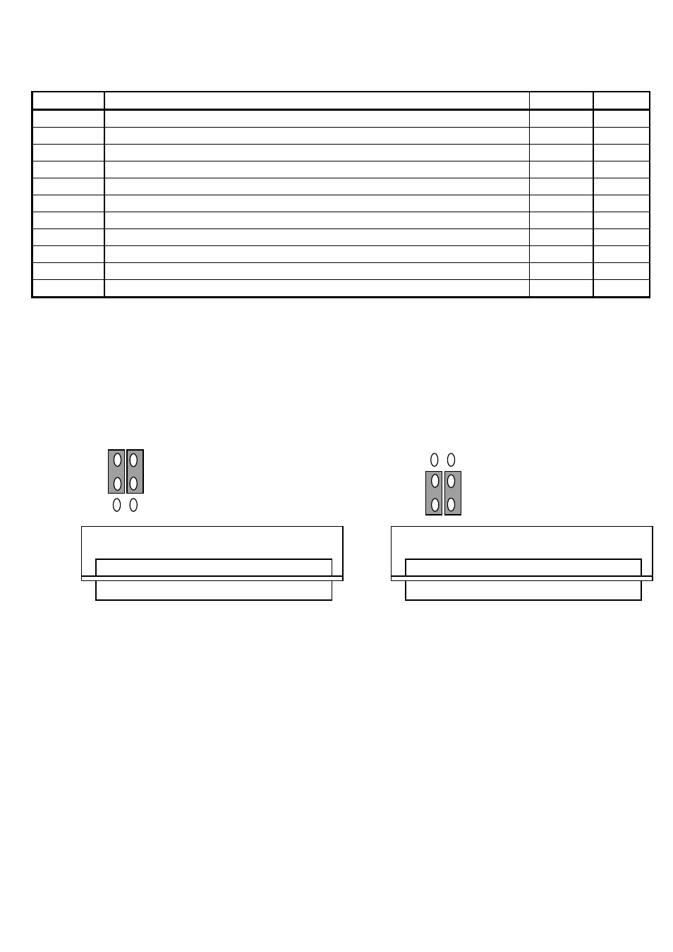
J7/J8 are positioned for eight injector drivers in fig 1 and 4 drivers in fig 2.
The E6S-8 (fig 1) should only be used with motors with more than 4 low
impedance injectors.
J7
J8
Fig 1
J7
J8 Fig 2
MAIN CONNECTOR
MAIN CONNECTOR
E.2.5 Hall Effect Sensors
The Haltech hall effect sensor is a two channel device that can be used to trigger the Haltech
range of ECU’s in a wide range of applications.
The most common application is in a direct fire configuration where a synchronisation event
is required. As the Haltech hall effect sensor is dual channel, it can provide this
synchronisation pulse as well as the trigger signal.
The principle behind its operation is quite simple. As a magnet passes the sensor the output
state changes from high to low. The orientation of the magnets determines the output signals
from the sensor.