Great Planes Super Decathlon 40 Kit - GPMA0185 User Manual
Page 30
on all sides (and front) with latex foam rubber. Leave a few
inches of extra fuel tubing in front of F-1 (you can cut off the
excess later). Please route the fuel tubing without making
tight bends, to prevent kinking. SUGGESTION: Access to
the fuel lines can be a problem in a cowled engine; therefore,
we suggest that you install some device for externally filling
and draining your tank, such as a Dubro #334 "Kwik-Fill"
fueling valve.
D 2. Secure the battery to the fuselage under the fuel
tank, just aft of F-2. The battery must be secure, but must be
surrounded by foam rubber to protect it from hard vibrations.
Therefore, after wrapping with foam rubber, we recommend
securing it to the fuselage with hooks and rubber bands.
D 3. Secure the receiver to the fuselage, just aft of the
battery, in the same manner.
D 4. Route the receiver antenna in one of the following
ways:
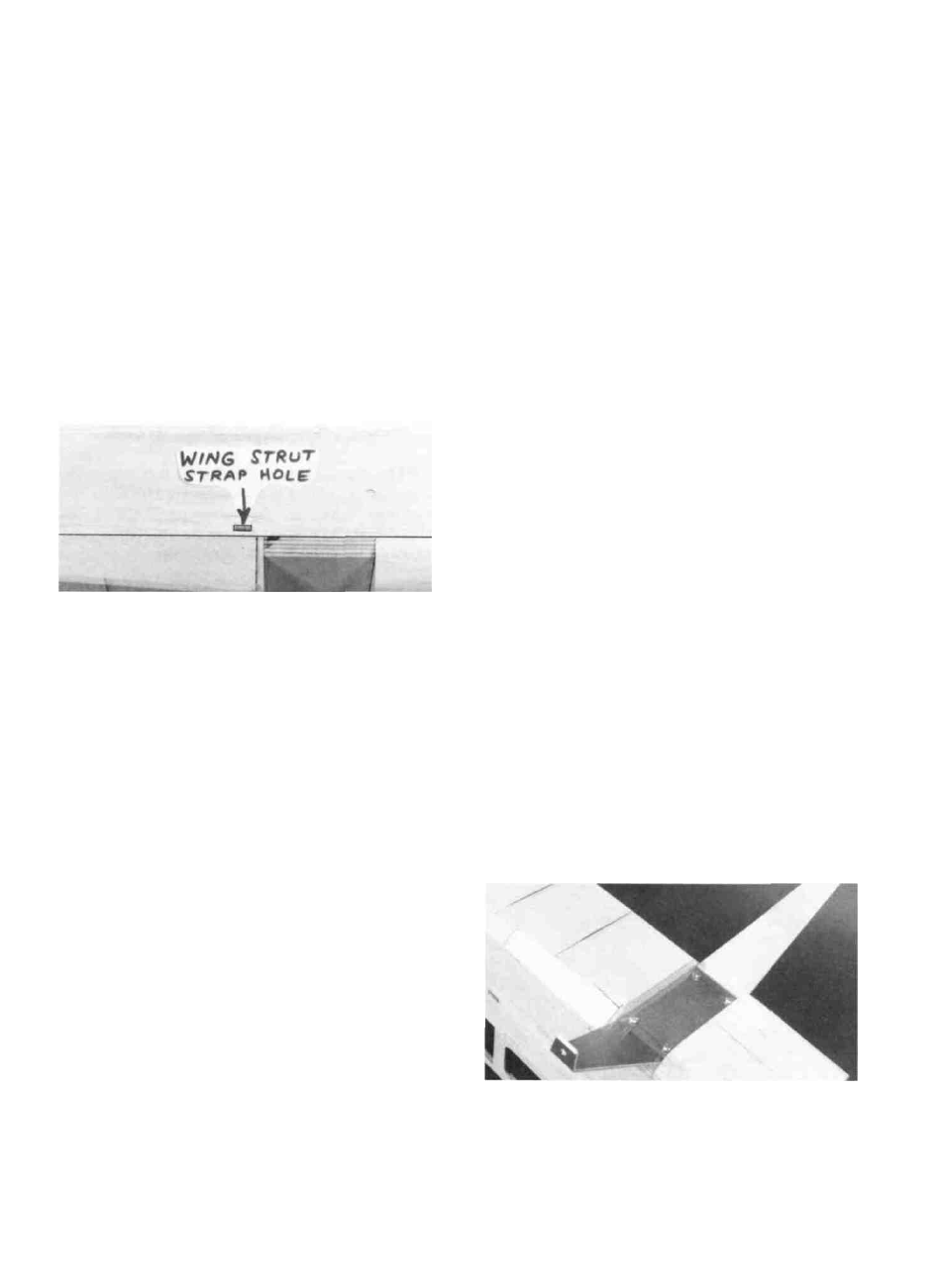
INSTALL WING STRUT STRAPS
D 1. Study the plans and, by measurement, mark the
wing strut strap locations on the fuse sides.
a. Route the antenna along the inside of the fuse side
and out of the fuse top, just behind F-4T. Anchor the
antenna to the top of the fin with a rubber band.
b. From the receiver, run the antenna directly through
the left fuse side just below the side windows, then
back to the stab.
c. Install another "pushrod guide tube" along the
inside of the fuse, along the bottom, exiting just
forward of the tailgear. Insert the antenna through
the tube,and leave the excess length trail behind.
D 5. From scrap 1/8" ply, make a small plate on which to
mount the on-off switch. Glue this plate to the front of F-3,
and run a 1/16" pushrod wire out the left side of the fuse. so
you can operate the switch without removing the wing.
D 2. Cut the slots by first drilling three 3/32" holes, then
use an Xacto knife to make the rectangular slots.
D 3. Enlarge one of the holes in six of the nylon straps,
using a 1/8" drill bit
D 4. Bend the nylon straps to the angle shown on the plan
by grasping them with a pliers, and pushing against a hard
surface.
D 5. Insert the ends of the straps which have enlarged
holes through the rectangular holes in the fuse sides, and tem-
porarily secure them to the fuse bottom with #4 x 3/8" sheet
metal screws.
NOTE: Do not mount the wing struts until after the
model is covered and the wing is installed in its final
position.
INSTALL RECEIVER, SWITCH AND
BATTERY
D 1. Wrap your receiver and battery in plastic bags, then
wrap with foam rubber.
INSTALL MAIN LANDING GEAR
D 1. Using a flat file, round the edges of the aluminum
main landing gear to remove all sharp edges.
D 2. Drill four 11/64" holes in the landing gear, using the
"Landing Gear Drilling Template" on the fuse plan.
D 3. Lay the landing gear in place on the bottom of the
fuselage, centered side-to-side. Use a pencil to mark the hole
locations on the 1/4" ply mounting plate. Drill 1/8" holes in
the mounting plate at these locations.
D 4. Secure the gear to the plate using the #8x1/2" sheet
metal screws.
30