Install the elevator & rudder servos – Great Planes Profile 38 - GPMA0487 User Manual
Page 31
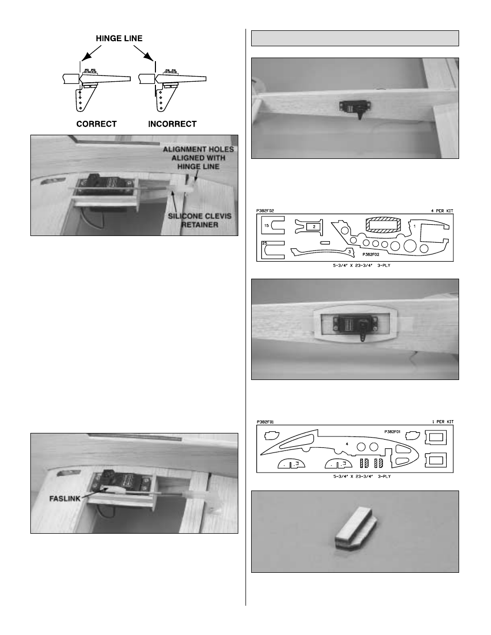
❏ ❏
4. Thread a nylon clevis approximately 14 full turns
onto the threaded end of a 2-56 x 4" [102mm] pushrod.
Slide a silicone clevis retainer over the clevis. Remove the
backing plate from one of the large control horns and
connect the clevis to the control horn. Position the control
horn on the aileron so that the adjustment holes are aligned
with the aileron hinge line and the pushrod is parallel with
centerline of the servo. Mark the control horn mounting hole
locations on the aileron.
❏ ❏
5. Attach the aileron control horn to the aileron with
two #2 x 1/2" [13mm] sheet metal screws. Remove the
screws and put a drop of thin CA in each hole to harden the
wood. After the CA has hardened, reinstall the control horn
with the screws.
❏ ❏
6. Center the aileron servo arm and mark where the
pushrod crosses the arm. Make a 90° bend at the mark, cut
the pushrod and attach it to the servo arm with a Faslink.
❏
7. Return to step 1,
Install the Aileron Servos and
install the other aileron servo.
❏ ❏
1. Using the hardware provided with the servo, install
the elevator servo in the servo tray of the left boom. Note its
orientation in the photo.
❏ ❏
2. Tape the die-cut 3-ply radiator housing mount to
the boom, centered around the elevator servo.
❏ ❏
3. Glue the die-cut 3-ply radiator tab to the radiator
tab base. Align the aft edge of the tab with the edge of the
tab base.
Install the Elevator & Rudder Servos
31