Set the control throws – Great Planes Nieuport XI EP ARF - GPMA1146 User Manual
Page 17
17
GET THE MODEL READY TO FLY
Center the Controls &
Check the Control Directions
Warning:
Once the battery is connected to the ESC, stay
clear of the propeller! Always stay behind the propeller!
❏
1.
Turn on the transmitter, center the trims, and move the
throttle stick all the way down. Plug your airplane’s battery into
the ESC and check to see that all servo arms are positioned
properly. If necessary, remove the servo arms from the
servos and reposition them so they are centered. Reinstall
the screws that hold on the servo arms.
❏
2.
With the transmitter and receiver still on, center
each of your control surfaces using a straight edge to
align each surface. Apply thread locking compound to
the locking screw threads and tighten all of the screw-
lock pushrod connectors.
❏
3.
Install the servo bay hatch using four 2 x 6mm [1/4"]
sheetmetal screws. Harden the screw holes and the holes in
the hatch with thin CA.
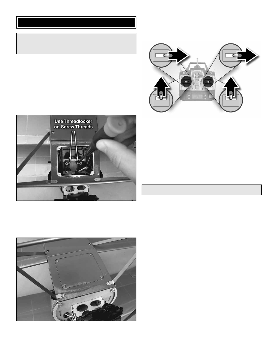
Full Throttle
Rudder
Moves Right
Elevator Moves Down
Right Aileron
Moves Up
Left Aileron
Moves Down
4-CHANNEL RADIO SETUP
(Standard Mode 2)
❏
4.
Make certain that the control surfaces and the throttle
respond in the correct direction as shown in the diagram. If
any of the controls respond in the wrong direction, use the
servo reversing in the transmitter to reverse the servos
connected to those controls. Be certain the control surfaces
have remained centered. Adjust if necessary.
Set the Control Throws
❏
1.
To ensure a successful fi rst fl ight, fl y your Nieuport
11 set up only according to the C.G. and control surface
throws specifi ed in this manual. The throws and C.G. are not
arbitrary, but have been determined through extensive testing
and accurate record-keeping. This provides you with the best
chance for success and enjoyable fi rst fl ights that should be
surprise-free. Additionally, the throws and C.G. shown are
true, real data which will allow the model to perform in the
manner in which it was intended when fl own by a pilot of the
skill level for which it was intended. DO NOT OVERLOOK
THESE IMPORTANT PROCEDURES. A model that is not
properly setup may be unstable and possibly unfl yable.
❏
2.
The building steps earlier in this manual that show
the mechanical setup for the elevator, rudder, and aileron
linkages show you the best way to confi gure the linkages to
achieve the proper throws using Futaba micro servos and a
Futaba radio system. If you are using a different radio system
or you cannot achieve the proper control throws using our
suggested linkage confi guration, you may have to install the
pushrods in different holes on the servo arms or the control
horns. Keep in mind that changing the throws mechanically
is preferred to changing them using your radio’s end-point
adjustment. End points should be used to “fi ne-tune” to get
the proper throws.