Great Planes Extra 300S 1.20 ARF Patty Wagstaff - GPMA1305 User Manual
Page 16
❏
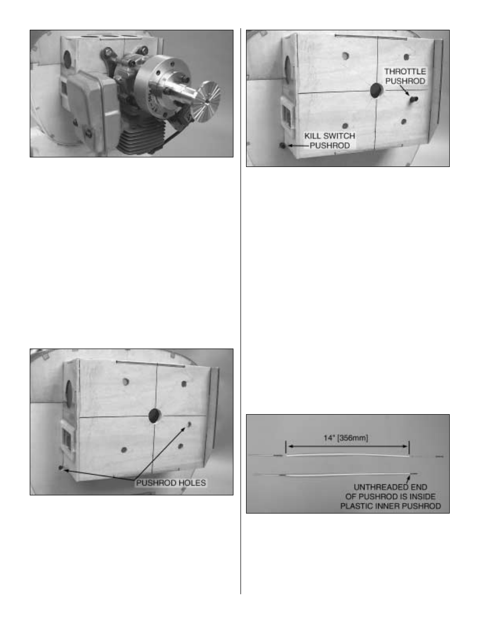
4. Install the engine in place with the hardware recommended
by the manufacturer. For the Fuji BT-50SA you should use
1/4-20 x 1" [25mm] bolts with 1/4-20 blind nuts and 1/4"
[6.4mm] flat washers. Note: Depending on the gas engine
you use, you may need to trim the firewall. For the Fuji
BT-50SA the sides of the firewall needed to be trimmed for
the muffler and for the carburetor’s fuel line.
Warning: All R/C equipment (receiver, batteries, servos and
switches) must be kept at least 12" [305mm] away from a
running gas engine. For this reason, the throttle servo and
the engine kill servo must be installed inside the fuselage. A
manual kill switch should also be installed.
❏
5. Mark the location of the throttle pushrod and of the kill
switch pushrod on the firewall. Remove the engine from the
firewall. Drill two 3/16" [4.8mm] holes through the firewall as
shown. Use a long drill bit to drill through the fuselage
formers. Make sure that you make the holes so that the
pushrods clear the wing tube and that they do not block the
wing mounting screws. Also, make sure you leave enough
space for the fuel tank. Note: The position of your throttle
pushrod and kill switch pushrod will vary depending on the
gas engine you use.
❏
6. Cut a 36" [914mm] plastic outer pushrod (not included)
so that you have one 19" [482mm] and one 17" [432mm]
long pieces. Roughen the ends of the outer pushrods and
use thin CA to glue them in place as shown in the above
image. Leave about 1/4" [6.4mm] of the engine kill pushrod
protruding, but cut the throttle pushrod flush with the
firewall. Note: If the throttle configuration on your Fuji
BT-50SA does not match the one you see in the previous
image, you may have to make changes to the throttle
pushrod location.
❏
7. To make the throttle pushrod you will need a 14"
[356mm] plastic inner pushrod, two 6" [152mm] threaded
one end pushrods a clevis, a clevis retainer and quick
connector. Thread a 6" [152mm] pushrod into each end of
the plastic inner pushrod as shown in the above image. Note
that the threaded pushrods are inserted in different
directions on each end. Make two of these pushrods, one for
the throttle and one for the kill switch.
16