Great Planes Extra 300S 1.20 ARF Patty Wagstaff - GPMA1305 User Manual
Page 14
[3.4mm]) drill bit. Tap the four holes with an 8-32 tap for the
engine bolts.
❏
6. Install the engine using four 8-32 x 1" [25mm] SHCS,
four #8 lock washers, and four #8 flat washers.
❏
7. Install the muffler for your engine. A Pitts-style Bisson
Custom Muffler (BISG4116) is being used on our prototype.
❏
8. Connect a 12" [25mm] servo extension to the throttle
servo and secure it with shrink tubing. Route the servo wire
to the center-section of the fuselage. Install the throttle
servo on its tray on the right side of the firewall box as
shown using the hardware supplied with the servo. Make
sure you wick thin CA into the servo screw holes of the
servo tray.
❏
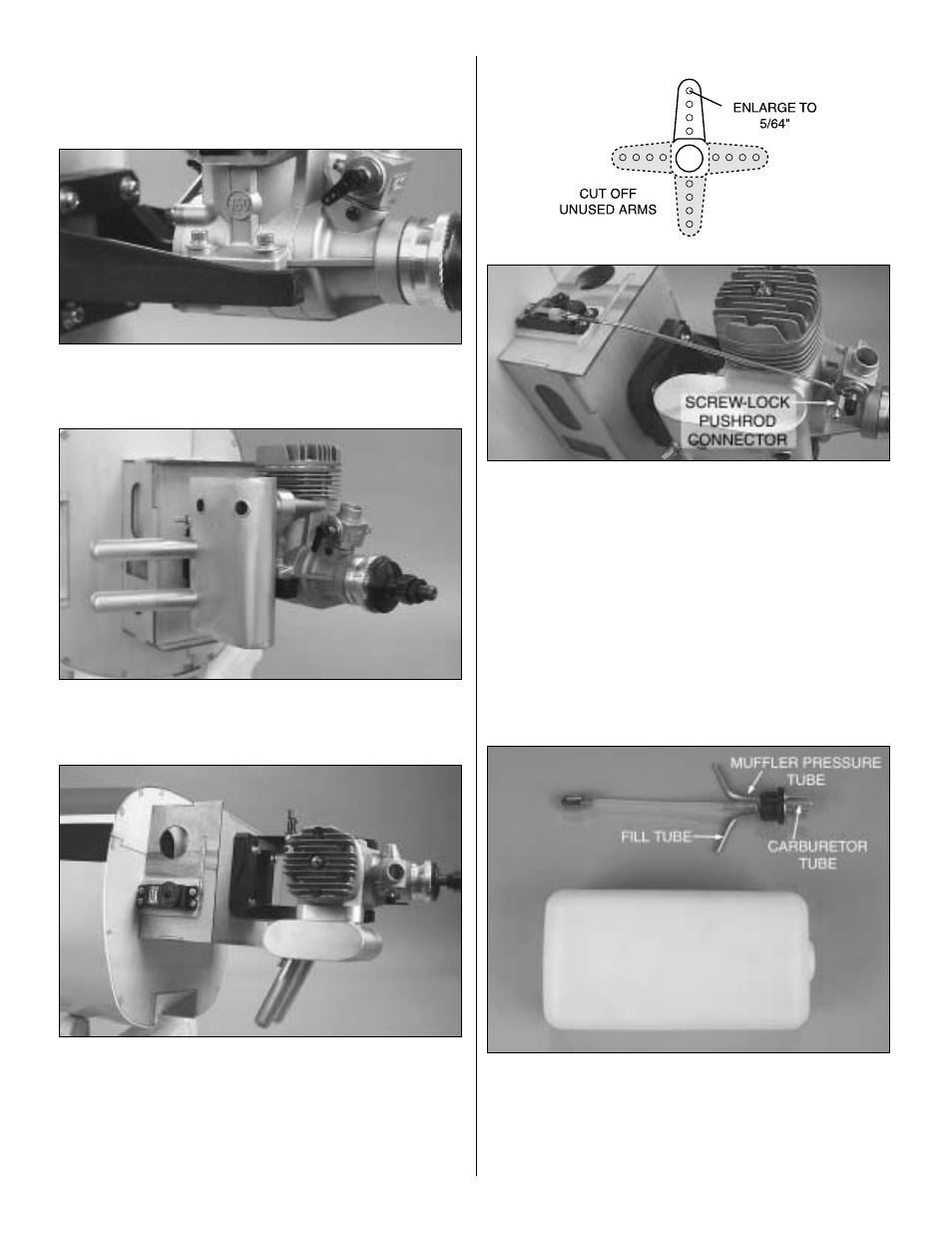
9. Cut a large servo arm as shown above, and install it
on the throttle servo. Install a 4-40 hex nut and a threaded
metal clevis on the threaded end of the 4-40 x 12" [305mm]
threaded one end pushrod. Connect the clevis to the throttle
servo arm. Slip a clevis retainer onto the pushrod. Install a
large Screw-Lock pushrod connector onto the carburetor
arm as shown. Bend the pushrod as necessary to clear the
engine head and muffler. The metal pushrod should not
touch the engine at any throttle setting. Connect the
pushrod to the carburetor arm with the Screw-Lock pushrod
connector. Use Great Planes Pro Threadlocker on the 4-40
x 1/4" [6.4mm] SHCS for the Screw-Lock pushrod connector
and tighten it. Reinstall the servo arm screw and tighten the
hex nut against the threaded clevis.
❏
10. Find the fuel tank. Assemble the stopper and tubes
as shown in the photo, and then insert them into the tank.
Do not tighten the screw to expand the stopper; you will do
that in the next step. Be certain the fuel line weight (clunk)
at the end of the fuel line inside the tank does not contact
the rear of the tank. Otherwise, the line may become stuck
14