Final hookups and checks – Great Planes Ultra Sport 60 Kit - GPMA0420 Pages 28-48 User Manual
Page 12
BALANCE YOUR MODEL
NOTE: This section is VERY important and must not be
omitted! A model that is not properly balanced will be
unstable and possibly unflyable.
1. Accurately mark the balance point on the bottom of
the wing on both sides of the fairing. The balance point is
shown on the plan (CG), and is located approximately 4-3/8
inches back from the leading edge. This is the balance point
at which your model should balance for your first flights.
Later, you may wish to experiment by shifting the balance up
to 3/8" forward or back to change the flying characteristics.
Moving the balance forward may improve the smoothness
and arrow-like tracking, but it may then require more speed
for takeoff and make it more difficult to slow down for
landing. Moving the balance aft makes the model more agile
with a lighter and snappier "feel" and often improves knife-
edge capabilities. In any case, do not balance your model
outside the recommended range.
2. With the wing attached to the fuselage, all parts of
the model installed (ready to fly), and an empty fuel tank,
block up the tail as necessary to level the fuselage. (If you
have built a tricycle gear, the fuse should already be sitting
level).
3. Lift the model at the CG marks. If the tail drops
when you lift, the model is "tail heavy" and you must add
weight to the nose to balance. If the nose drops, it is "nose
heavy" and you must add weight to the tail to balance.
NOTE: Nose weight may be easily installed by using a
Prather "Spinner Weight'' (available in assorted weights, up
to 2 ounces), or by gluing strips of lead into the engine
compartment under the engine. Tail weight may be added by
using Prather "slick-on" lead weights, and, later, if the
balance proves to be OK you can open the fuse bottom and
glue these in permanently. NOTE: Try shifting the location
of the radio components to balance the airplane, before
actually adding weight
FINAL HOOKUPS AND CHECKS
direction as illustrated in the sketch at the top of the next
column.
2. Adjust your pushrod hookups as necessary to pro-
vide the proper control surface movements as listed on Page
35.
*NOTE: These control surface "throws" are approximate
and provide a good starting point for the first flights with your
Ultra Sport 60. You may wish to change the throws slightly
to provide the smoothness or quickness that you prefer.
3. Check for wing twist as follows:
NOTE: Even if you have built your wing on a perfectly flat
surface and used utmost care, it is possible that your wing may
have a twist due to uneven shrinking of the covering material.
You must check for this condition and correct it before the
first flight.
If you do not own a wing incidence meter, we recom-
mend that you purchase one from your local hobby dealer or
borrow one from another modeler. With the wing mounted to
the fuselage, use the incidence meter to check the angle of
your wing at the root and at the tips. If the incidence meter
reveals a wing twist of more than 1/4 degree, you must grasp
the wing at the tip and twist it slightly, while reheating the
covering material. Keep checking, twisting and reheating
until the wing twist is removed. NOTE: If you have
corrected a wing twist by this method, you should periodi-
cally re-check to make sure the correction has held.
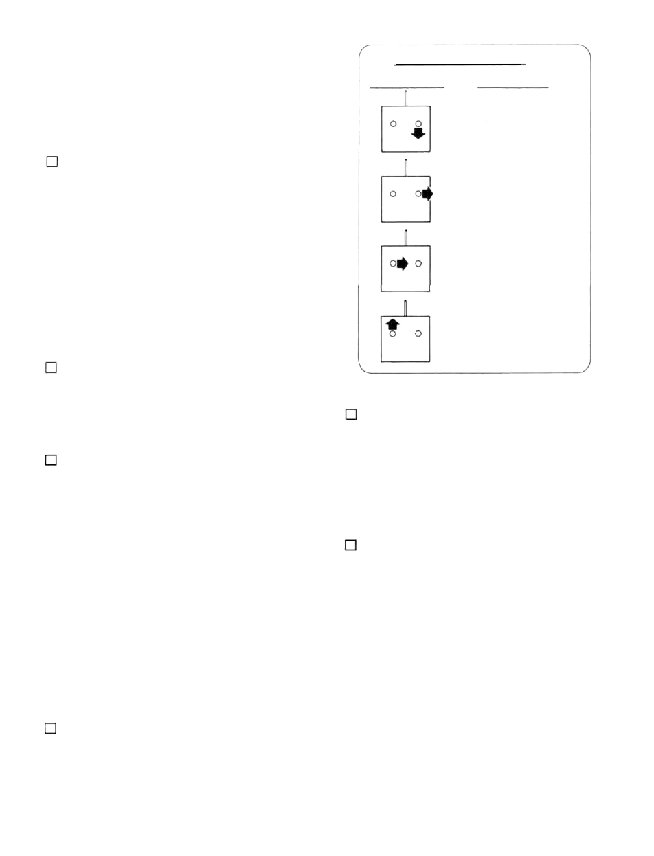
FOUR-CHANNEL SETUP
TRANSMITTER
STICK MOVEMENTS
CONTROL SURFACE
MOVEMENTS
ELEVATOR MOVES UP
RIGHT AILERON MOVES UP
LEFT AILERON MOVES
DOWN
RUDDER MOVES RIGHT
NOSE WHEEL TURNS RIGHT
CARBURETOR WIDE OPEN
1. Make sure the control surfaces move in the proper
39