Great Planes Ultimate Biplane 40 Kit - GPMA0240 User Manual
Page 40
D 4 Without cutting into the balsa, use a sharp hobby knife
to carefully cut and remove a strip of covering 1/16" wide,
approximately 1/32" inside of the line you made Wipe away
the line with a paper towel dampened with alcohol.
D 5 Reposition the canopy on the fuse and confirm that it
covers the exposed wood Glue the canopy to the fuse with
a glue formulated for gluing on canopies such as Pacer
"Formula 560" canopy glue Hold the canopy in place with
masking tape or rubber bands.
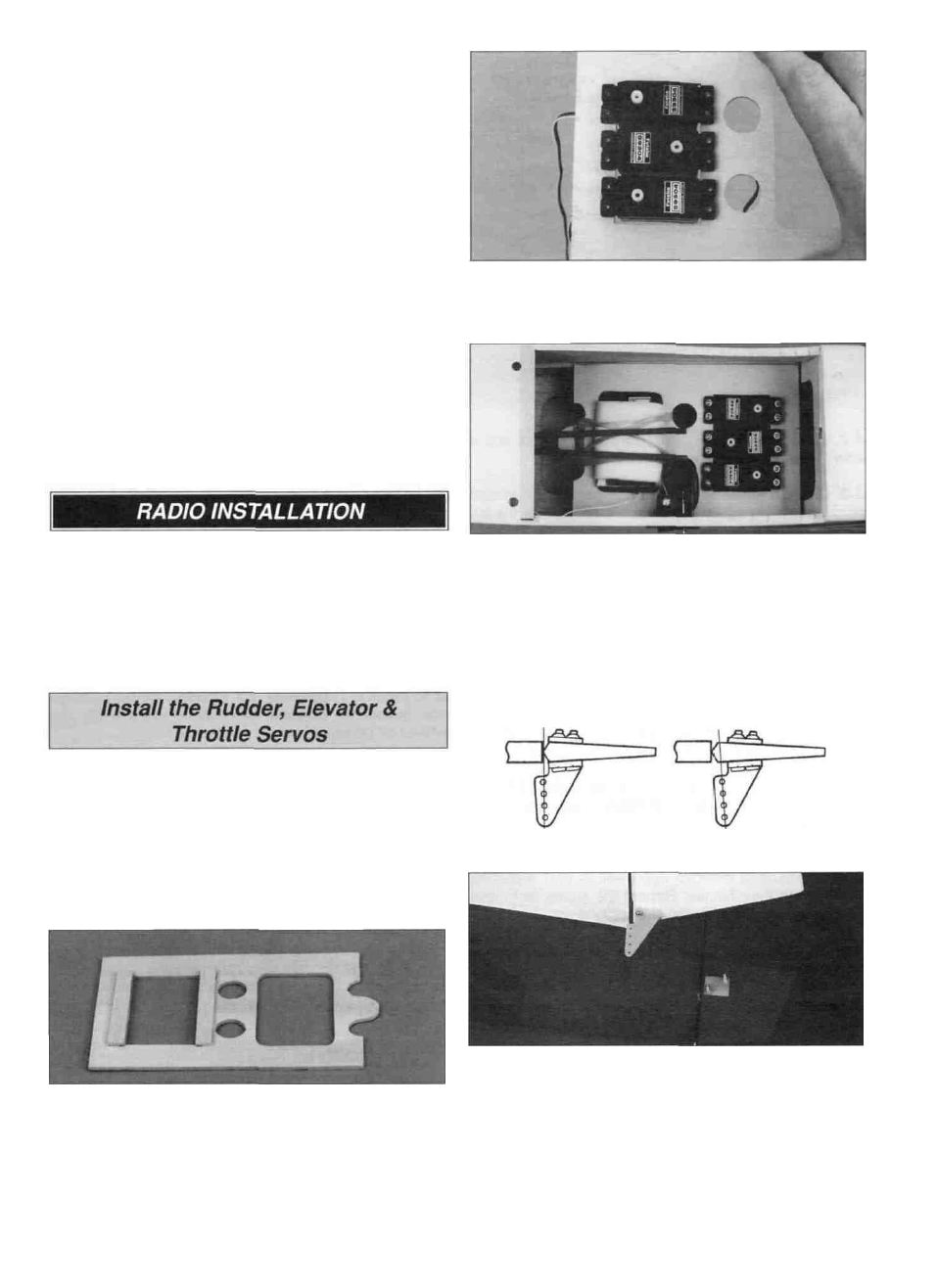
D 3 Install the servos in the servo tray as shown, spacing
them apart as necessary so the servo arms do not interfere
with each other.
With the Ultimate completely assembled except for the
radio system, turn to page 44 and check the balance point
of the plane The radio tray can be installed with the servos
forward or aft If the plane is tail heavy, install the servo
tray with the servos forward ^ If the plane is nose heavy,
install the servo tray with the servos aft.
D 4 Plug the servos into the receiver Wrap the receiver in
foam padding and rubber band it in the servo tray Insert
the servo tray under the outer pushrod tubes and glue it in
position Install the receiver switch and plug the receiver
battery into the receiver.
D 5. Cut the outer pushrod tubes 2" short of the rudder
and elevator servos.
D 1. After determining the location for the servos, test tit
the die-cut 1/8" plywood servo tray in the fuse The edges
of the servo tray will need to be sanded to allow it to fit on
the lip created by the top forward fuse doubler The servo
tray is installed as far forward as possible, even with the
servos at the aft end.
D 2 Glue the die-cut 1/8" plywood servo tray doublers to
the bottom of the servo tray, flush with the edges of the
servo cut-out.
RIGHT WRONG
D 6 Position the large control horns on the elevator and
rudder as shown in the sketch and on the plan Mark the
location of the mounting holes and drill a 3/32" hole at the
marks Mount the control horns on the rudder and elevator
with the backing plate and 2-56 x 5/8" screws.
40