Great Planes Ultimate Biplane 40 Kit - GPMA0240 User Manual
Page 39
It is best to leave a very slight hinge gap rather than
closing it up tight, to help prevent the CA from wicking
along the hinge line Make sure the control surfaces will
deflect to the recommended throws without binding If
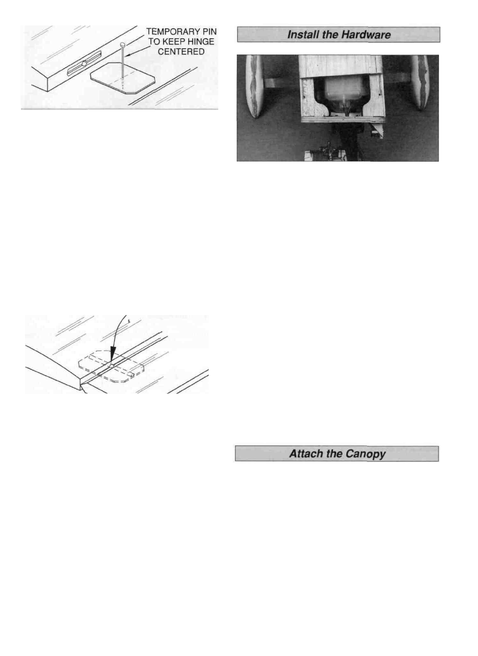
you have cut your hinge slots too deep, the hinges may
slide in too far leaving only a small portion of the hinge
in the control surface To avoid this you may insert a
small pin through the center of each hinge before
installing This pin will keep the hinge centered while you
install the control surfaces.
D 2 Clean the elevator joiner wire with alcohol and a
paper towel to remove any oil residue
D 3 Glue the joiner wire in the elevators with 6-minute
epoxy Before the epoxy cures, tape a flat stick to the left
and right side of the stab and to the elevators This will
ensure that both elevators are even
ASSEMBLE THEN APPLY 6 DROPS
OF THIN CA TO CENTER
OF HINGE, ON BOTH SIDES
D 4 Apply 6 drops of thin CA adhesive to both sides of
each hinge Allow a few seconds between drops for the CA
to wick into the slot
D 5 Pack each of the torque rod holes in the ailerons with
30-minute epoxy (a toothpick works well for this) Install the
ailerons with their hinges Repeat the gluing technique
described previously and allow the epoxy to cure.
D 6 Cut a slot in the TE of the fin for the tailwheel bracket
nylon bearing
D 7 Lightly coat the tailwheel wire with petroleum jelly
where it enters the nylon bearing This will prevent the wire
from becoming glued to the bearing
D 8 Pack the tailwheel bracket hole in the rudder and the
slot in the TE of the fin with 30 minute epoxy Install the
rudder with i t s hinges Repeat the gluing technique
described previously and allow the epoxy to cure
D 1 Assemble the fuel tank according to the manufacturer's
instructions Remove the fuel tank hatch Place 1/4" foam
padding (not included) on the tank floor Insert the fuel tank
into the fuel tank compartment If using the Great Planes
10oz fuel tank place a piece of foam padding at the front of
the tank Insert a piece of foam padding between the tank
and the top deck Also glue a piece on the bottom of the fuel
tank hatch Insert two 12" pieces of fuel tubing (not included)
through the firewall Connect one of the fuel tubes to the fuel
pick-up fitting and the other to the pressure fitting
D 2 Reinstall the landing gear with 6 32 x 1/2" cap head
screws and #6 washers Reinstall the engine mount and
engine Apply thread lock to the bolts holding the engine to
the firewall and the landing gear to the fuse
D 3 Shorten and connect the fuel pick-up line to the
carburetor (or fuel fill valve) Connect the pressure line to
the muffler
D 4 Install a 1" tailwheel (not included) on the tailwheel
wire Secure the tailwheel with a 3/32" wheel collar and
4-40 x 1 /8" set screw
D 5 Reinstall the cabane on the fuse Apply thread lock to
all the 4-40 x 3/8" bolts when reassembling the cabane.
D 1 Before permanently installing the canopy, securely
glue your pilot in place on the cockpit floor For the most
security, in addition to glue secure the base of the pilot to
the cockpit floor with a #4 sheet metal screw (not included)
from the underside of the cockpit floor
D 2 Place the canopy on the fuselage in the location
shown on the plan Temporarily hold it in position with tape
or rubber bands
D 3 Use a felt tip pen to accurately trace the canopy outline
onto the MonoKote film Remove the canopy
39