Great Planes U-Can-Do 3D 60 ARF - GPMA1270 User Manual
Page 19
❏
7. Thread a clevis 25 turns onto one end of each of the three
12" [305mm] pushrods. Slip a silicone retainer over the clevises.
❏
8. Make three one-arm servo arms. Enlarge the holes in
the arm with a Hobbico Servo Horn Drill (or a #48 or 5/64"
(2mm) drill bit) so the pushrod will fit.
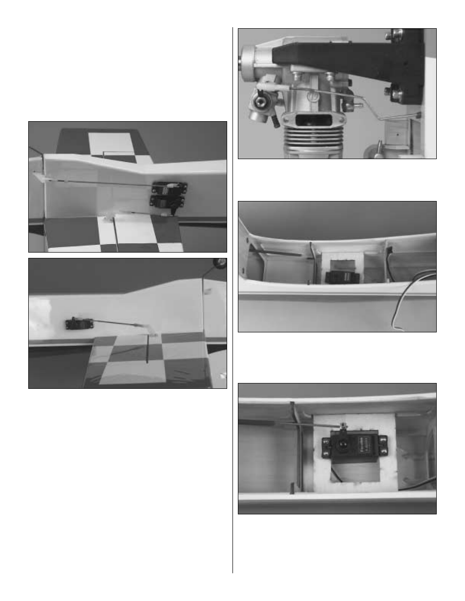
Use these photos for the next three steps. NOTE: The
photos depict a radio setup that does not have mixing. If
your radio has twin elevator mixing, mount both servo arms
towards the stab.
❏
9. Connect the servo leads to the receiver. Turn on the
transmitter and receiver to center the servos. Attach the
servo arms to the servos 90 degrees to the servo.
❏
10.Attach the clevises with pushrods to the control horns.
Hold the control surfaces straight and mark the pushrods
where they cross the servo arms. Bend the pushrods 90
degrees away from the fuse on the marks you made. Turn
the receiver and transmitter off.
❏
11. Attach the pushrods to the control horns as shown.
Trim the pushrod, being certain to leave 1/16" [1.6mm] of
wire protruding from the Faslinks.
❏
12. Screw a clevis 10 turns onto the end of the 17-1/2"
[445mm] throttle pushrod. Bend the pushrod as necessary
for a smooth action.
❏
13. Glue the servo tray in place with medium CA, as
shown in the photo. Fit the throttle servo in the tray but do
not screw it in place at this time.
❏
14. Connect the throttle pushrod to the throttle servo with
the screw-lock connector.
❏
15. Let the pushrod locate the servo in the tray. Mount
the servo to the servo tray with the hardware provided with
your servo.
19